 DWG
DWG
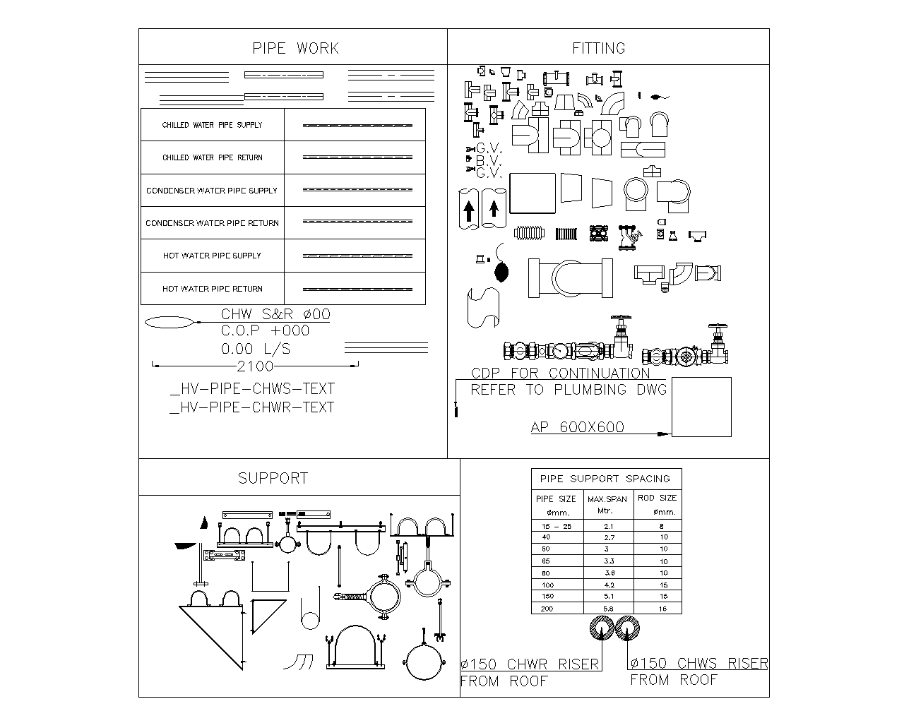
HVAC Chilled Water Legend — Pipe Work, Fittings and Supports Dynamic Blocks
Three-panel HVAC legend sheet covering chilled water, condenser water and hot water pipe line types, a full fitting and valve block set, and pipe support arrangements with a support spacing and rod size table. All blocks are dynamic.
Screenshots
About
What this drawing shows
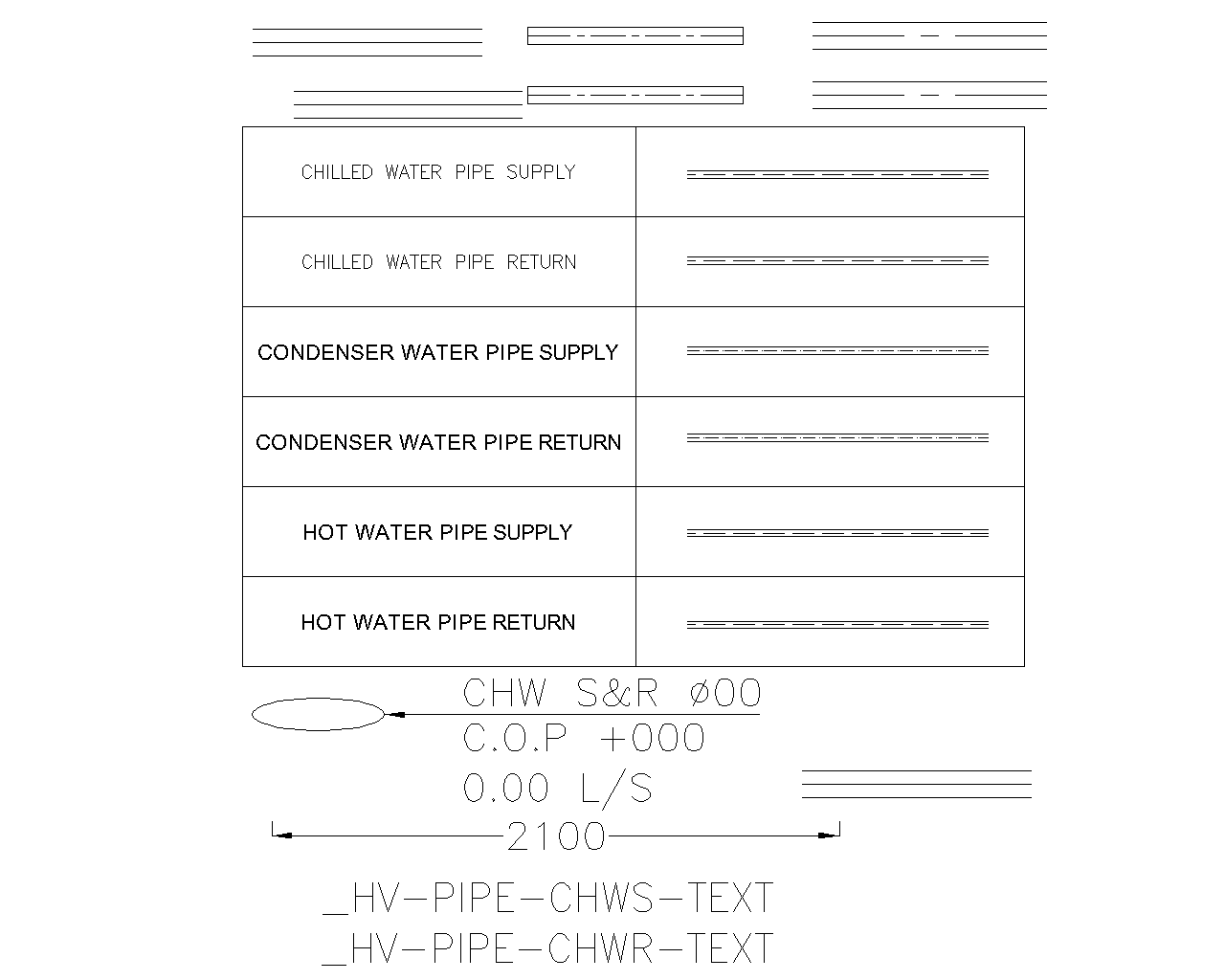
A three-panel legend sheet for chilled water and condenser water systems. The pipe work panel sets out line types for chilled water supply and return, condenser water supply and return, and hot water supply and return, together with the pipe annotation block showing size, centre of pipe level and flow rate, and the layer names the text belongs to.
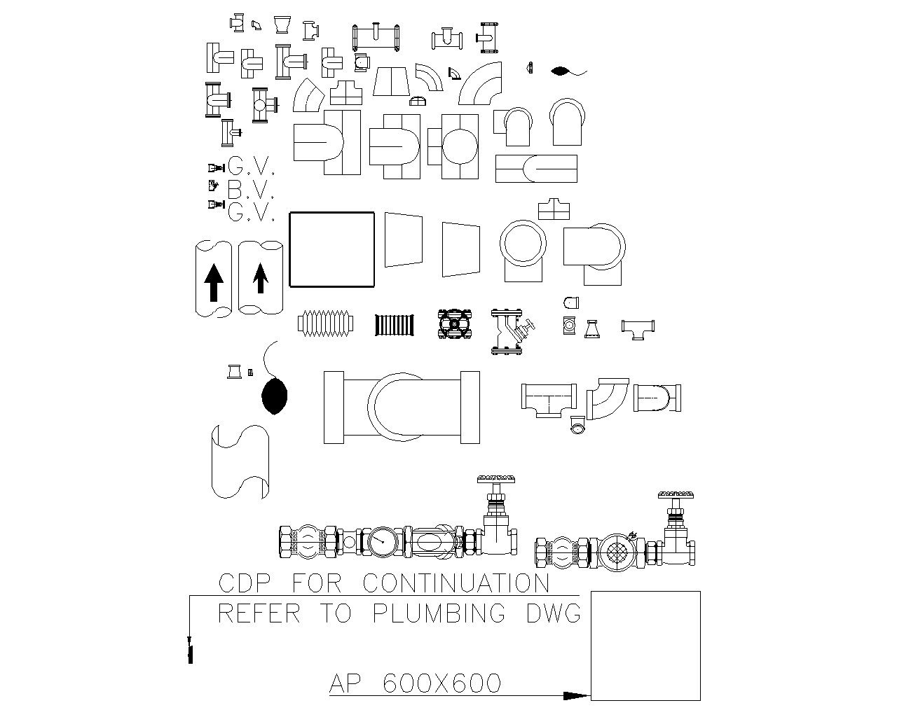
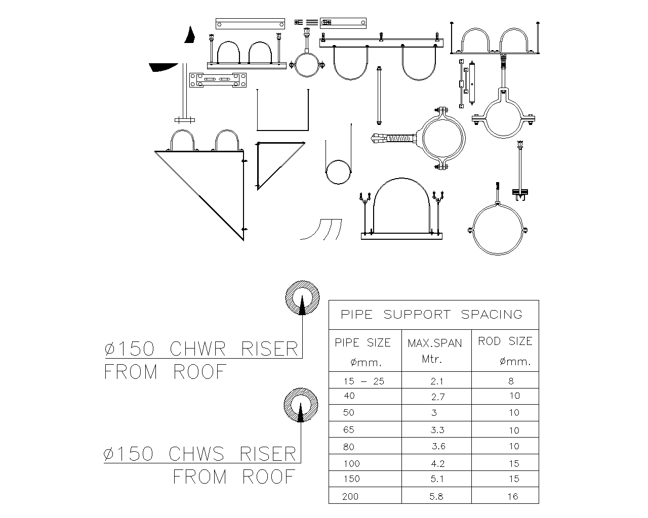
The fitting panel holds the valve and fitting set in both plan and elevation — gate, butterfly and globe valves, flanged and screwed connections, reducers, elbows, tees, flexible connectors, strainers, expansion joints, gauges and a pump set assembly drawn with its isolation and check valves. The support panel covers trapeze hangers, split ring and clevis hangers, riser clamps, U-bolts, clamp assemblies and wall brackets, with a pipe support spacing table giving maximum span and rod size against pipe diameter.
All blocks in this file are dynamic. Sizes, orientations and configurations can be driven from the block properties rather than by exploding and editing, which keeps the set consistent across a drawing and makes it far easier to keep a project legend matching what is actually drawn on the plans.
Working with dynamic blocks
The advantage of a dynamic set is also the thing that catches people out. Because a dynamic block carries multiple states, a single block reference can look like a 50 mm gate valve on one plan and a 150 mm butterfly valve on another, and a schedule extracted from block name alone will not tell them apart. If you count or schedule from these blocks, extract the dynamic properties, not just the name. Check this before you build any quantity take-off on the file.
Do not explode them. Exploding a dynamic block to force one variation is the usual site-office shortcut and it breaks the link to every other instance, so the next time a valve size changes globally you are editing by hand. If a configuration you need is missing, add it as a visibility state or a lookup parameter in the block editor rather than working around it. Also check the annotation behaviour before you issue: if the text inside a block is not annotative, it will not scale with the viewport and your legend will read correctly at one scale and badly at another.
Notes on using the legend
A legend sheet is only useful if it matches the drawings it sits with, and the most common review comment on MEP submittals is a legend showing symbols that do not appear on any plan, or plans using symbols the legend never defines. Strip the unused entries before issuing rather than leaving the full library on every sheet. The reviewer reads the legend as a statement of intent, and a padded one invites questions you do not want.
The line types here distinguish chilled water supply from return, and condenser water from both. Keep that distinction in the layer structure as well as the line type — the layer names shown on this sheet follow a discipline and service convention, and once the plot style is applied, supply and return need to remain distinguishable in black and white print. Colour-only differentiation reads perfectly on screen and disappears entirely on a printed submittal or a scanned site copy, which is how most of these drawings are actually used.
On the pipe annotation block, the centre of pipe level is the field that earns its place. Chilled water mains, drainage, cable containment and ductwork all compete for the same ceiling void, and a plan that gives sizes but no levels pushes the entire coordination problem to site. Fill the level in at the point you draw the run, not later.
Support spacing table
The table on this sheet gives maximum span and hanger rod size against pipe diameter. Treat it as a starting point for the specific pipe material and service it was prepared for, and confirm it against the standard governing your project before relying on it. Support spacing depends on pipe material, wall thickness, operating temperature and whether the pipe is water-filled in service, and a table drawn up for steel pipe will not suit copper, plastic or pre-insulated pipe. The spans also assume the pipe is straight and uniformly loaded — concentrated loads change the picture entirely.
Three things routinely go wrong on site regardless of what the table says. Valves, strainers and flanged fittings need a support close to them rather than mid-span, because that weight is not distributed. Changes of direction need support near the elbow so the fitting is not carrying the run. And on insulated chilled water lines, the hanger must bear on a load-bearing insulation insert and shield rather than clamping directly onto the pipe — clamping the bare pipe crushes the insulation where it is fitted later, creates a thermal bridge at every support, and the pipe then sweats and drips at exactly those points. It is a defect that shows up months after handover and is expensive to reach.
Where hangers and supports are fixed to a fire rated slab or pass through a fire rated assembly, check the fixing and any penetration against the local requirement. Saudi Civil Defence requirements may be stricter than the referenced standard, and anchor selection into post-tensioned slabs needs agreeing with the structural engineer rather than being decided at first fix.
Drawing use
- Legend and symbol sheets for chilled water and condenser water drawings
- Shop drawings and coordination plans needing a consistent fitting and valve set
- Typical support details and hanger schedules
Confirm the support spacing table against your project specification and pipe material before issuing, and remove unused legend entries from the sheet.