 DWG
DWG
AHU and Smoke Extract Fan Installation Detail — Control Panel and Cabling
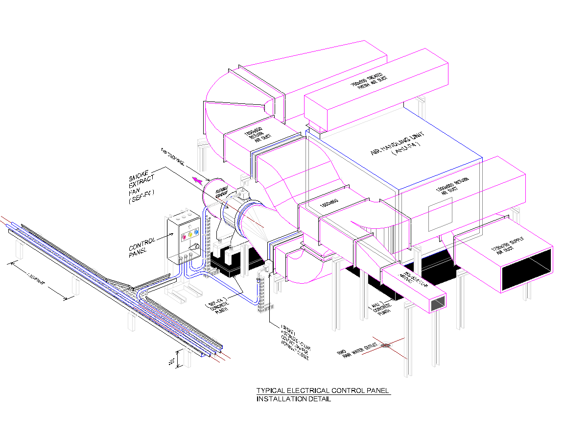
Isometric of a plant room installation showing an air handling unit with fresh air, return and supply ductwork, a smoke extract fan on its own plinth, and the local control panel with its power and control cabling routed from a…
About
What this drawing shows
An isometric of a plant room installation drawn as a single coordinated view. The air handling unit sits on a concrete plinth with treated fresh air, return air and supply air ducts connected, each annotated with its size, and a condensate drain from the unit. A smoke extract fan sits on its own plinth, connected through a flexible connector, with the discharge ductwork run away from the unit.
The electrical side is drawn as well. A local control panel is mounted beside the fan, with conduit and cabling dropping into a cable trench that runs across the plant room floor, and separate routes shown for the power supply cables, the smoke extract fan cabling and the control wiring. The trench is dimensioned in width and depth. The detail is intended for plant room layouts where the mechanical and electrical installation have to be shown together.
Installation notes
A smoke extract fan is life safety equipment, and its supply and control arrangements are what separate it from an ordinary extract fan. Its power supply must be fire rated and routed so that a fire in one compartment cannot disable the fan serving another; that affects the cable type, the trench route and the position of the panel. The fan must start on a command from the fire alarm system, and the control panel needs an interface with a monitor module or control module wired back to the fire alarm panel, with the sequence recorded in the cause and effect matrix. It also needs a local means of isolation for maintenance that cannot leave the fan disabled in a fire — a lockable isolator with position monitoring is the usual answer. The fan and its motor must be rated for the temperature and duration the standard requires for smoke extract duty, which is not the same as a comfort ventilation fan.
The AHU and the smoke extract fan behave in opposite directions during a fire, so the interlock between them is a design item, not a site decision. The AHU normally shuts down when the fire alarm operates, and the fire and smoke dampers in its ducts close, while the smoke extract fan starts. Where the AHU serves more than one compartment, shutdown and damper operation are zoned rather than global. Every fire and smoke damper in this ductwork needs an access panel within reach of the linkage, and those panels have to be shown on the drawing and coordinated with the ceiling layout before it is set out — a damper sealed behind plasterboard is the commonest Civil Defence inspection finding in the Kingdom.
On the mechanical side, flexible connectors on both fan and AHU connections are there to keep vibration out of the ductwork, and they only work if the ducts either side are independently supported so the connector is neither stretched nor compressed. The inertia bases or anti-vibration mounts shown under the units need to be selected for the operating weight of the running unit, not its shipping weight. The condensate drain needs a trap sized for the fan pressure and a continuous fall to a drain that can take the flow; on a unit under negative pressure, an untrapped or undersized drain simply holds water in the pan, which is where the smell and the overflow come from months after handover.
Plant room coordination is what the trench is for. Keep power, control and fire alarm cabling segregated within the trench, either in separate compartments or with the spacing the specification requires, and make sure the trench cover is flush, rated for the traffic and removable without lifting equipment. Leave working space in front of the control panel to the clearance required by the electrical code, measured from the panel face to whatever is opposite — a panel that ends up behind a duct is a rework item found at inspection. Installation should follow the standards governing your project, including NFPA 90A and the fire alarm standard for the interlocks, and local Civil Defence requirements may be stricter.
Drawing use
- Plant room layouts and equipment installation drawings
- Method statements for AHU and smoke extract fan installation
- Coordination between mechanical, electrical and fire alarm trades
Replace the unit outlines with the certified dimensions of the selected equipment, and confirm cable types, fire ratings and interlock sequences against the project specification before issuing.