 DWG
DWG
Electrical Typical Installation Details — Complete 7-Sheet Set
A complete set of seven electrical typical detail sheets from a building project, covering accessory mounting heights, distribution boards, containment and supports, fire alarm and emergency lighting devices, earthing, lightning protection and fire stopping, in one DWG.
Screenshots
About
What is in this set
Seven sheets of electrical typical details prepared for a building project, supplied together in one DWG. Between them they cover the installation details a contractor’s shop drawing package usually needs: where accessories go, how boards and containment are fixed, how fire alarm and emergency lighting devices are installed, and how the earthing and lightning protection systems are built into the structure. Each sheet is described below.
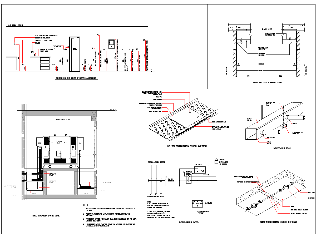
Sheet 1 — Accessories, transformer room and containment
Standard mounting heights of electrical accessories in elevation, hand dryer termination under fixed and demountable ceilings, a section through a transformer room with cable trenches and earthing, cable tray and conduit crossing building expansion joints, GI cable trunking with conduit connections, and external lighting control by time clock and photocell.
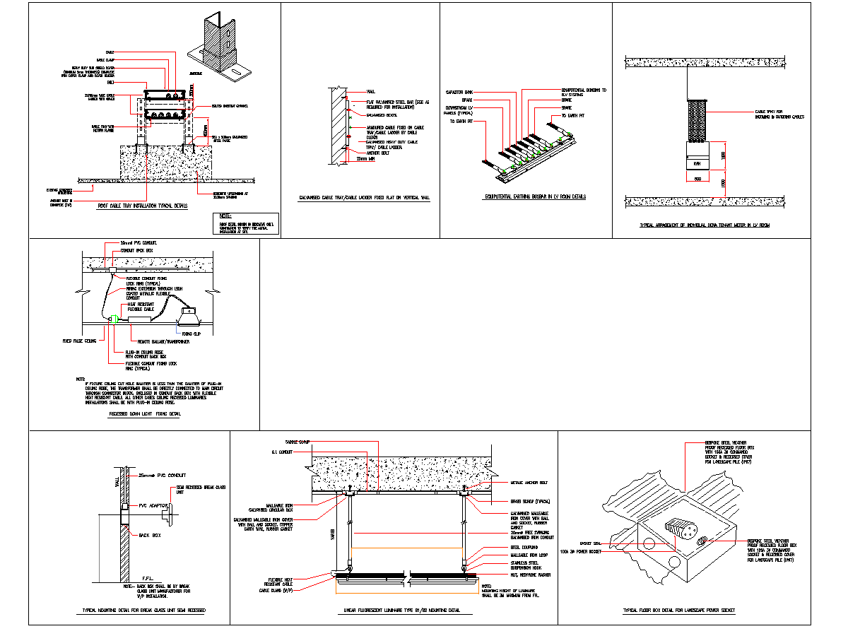
Sheet 2 — Roof containment, LV room and luminaires
Roof cable tray installation on plinths, cable tray fixed flat on a vertical wall, the equipotential earthing busbar in the LV room, the arrangement of tenant kWh meters, recessed downlight fixing, a semi-recessed break glass unit, linear luminaire suspension, and a weatherproof floor box for landscape power sockets.
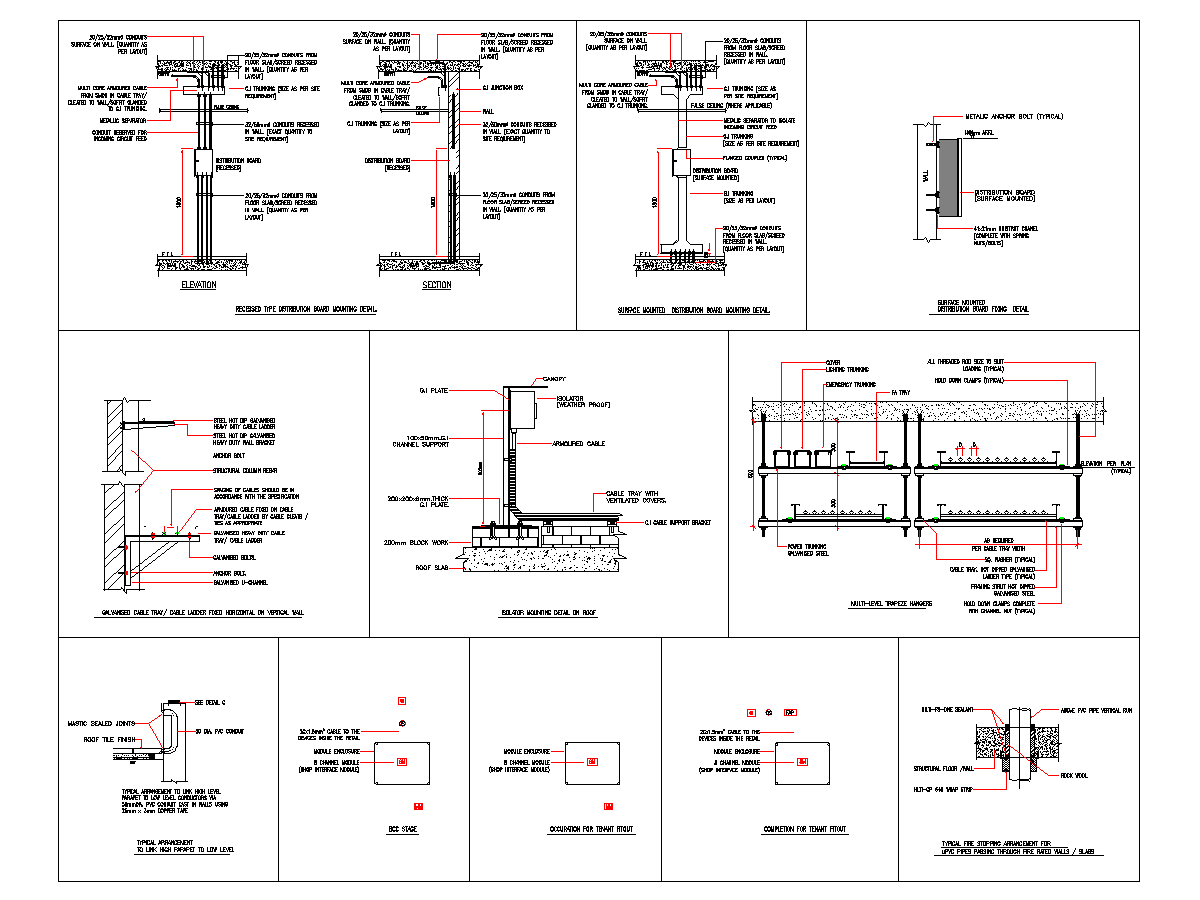
Sheet 3 — Distribution boards, supports and fire stopping
Recessed distribution board mounting in elevation and section, surface mounted board mounting and fixing, cable ladder fixed horizontally on a wall, a weatherproof isolator on the roof, multi-level trapeze hangers carrying power, lighting, emergency and fire alarm containment, the link between high parapet and low roof level, fire alarm module enclosure stages for tenant fit-out, and fire stopping for uPVC pipes through fire rated walls and slabs.
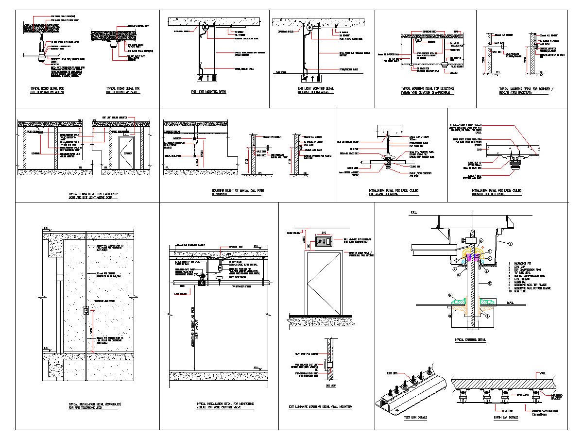
Sheet 4 — Fire alarm, emergency lighting and earthing
Fixing details for fire detectors on ceilings, slabs and in false ceiling voids, exit and emergency light mounting, sounder and beacon mounting, manual call point and sounder mounting heights, a concealed fire telephone jack, the monitor module for a sprinkler zone control valve, a wall mounted exit luminaire, an earth pit connection through a membrane-sealed slab, and test link and earth bar details.
Sheet 5 — Lightning protection components
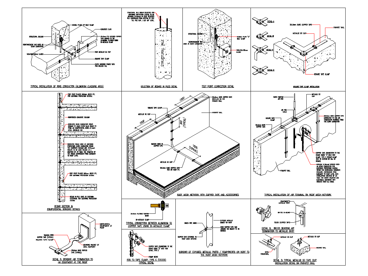
The ring conductor on aluminium cladding, selection of rebars in piles, test point connections, square tape clamps, rebar down conductors with equipotential bonding at each floor, the roof mesh network in copper tape, air terminals on the mesh, bi-metallic connections, rod-to-tape clamps, and bonding of roof equipment and exposed metalwork.
Sheet 6 — Lightning protection scheme and earth pit
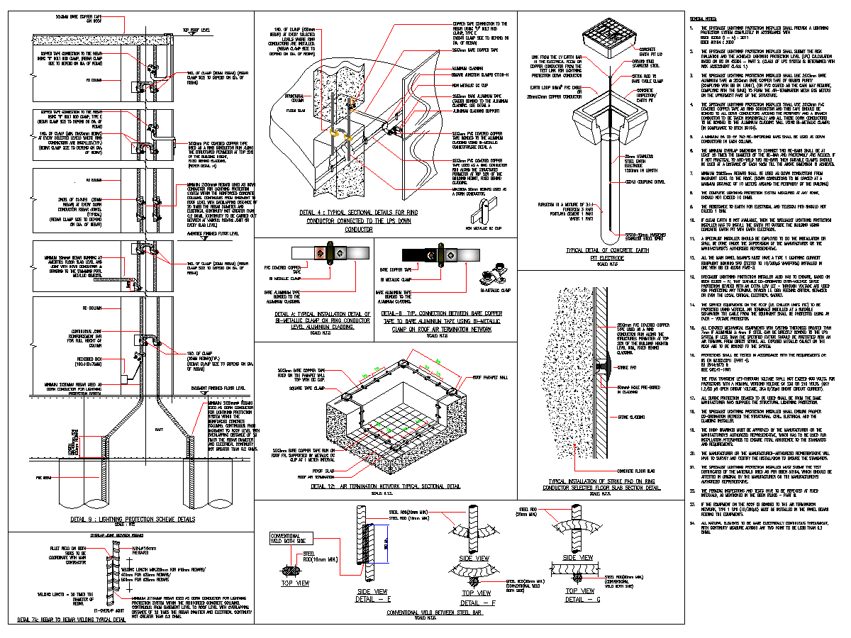
The lightning protection scheme through the building height, ring conductor sections at the cladding, bi-metallic clamp details, the air termination network in section, a concrete earth pit with electrode, a strike pad on the ring conductor, rebar-to-rebar welding and conventional weld details, and a full column of general notes for the specialist installer.
Sheet 7 — Foundation earthing and down conductors
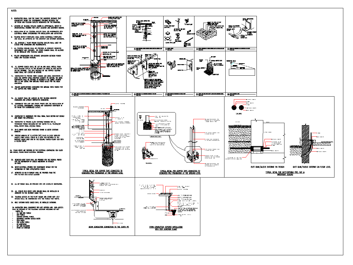
Copper tape connected to dedicated pile foundations, down conductor connection to the earth pit, exposed down conductor installation with test junction clamp, duct and sleeve sealing against fire, gas and water where cables enter the building, and general notes for telecom cabling.
Installation notes
Where the lightning protection system uses the structural reinforcement as down conductors, continuity has to be proved during construction, not after. Once the next pour closes over a column, a broken path between rebars cannot be found or fixed, so test each lift as it is built and record the readings against the limits in the general notes. Agree the joining method with the structural engineer before the first cage is tied: many engineers will not accept welding of reinforcement because heat can change the properties of the bar, and the clamped alternatives shown on these sheets exist for exactly that reason. Leave the test points at the heights shown and keep them accessible after finishes, because an inaccessible test point turns the periodic inspection into a demolition job.
Copper and aluminium must never touch directly. Where the copper ring conductor meets aluminium cladding or an aluminium tape, the joint goes through a bi-metallic clamp, as detailed; direct contact corrodes galvanically, and on coastal sites in Jeddah or Dammam that happens within a few years. On the roof, every piece of metal equipment has to be bonded to the air termination network or kept at a calculated separation distance from it. The usual commissioning finding is plant added by another trade after the roof mesh was installed and never bonded. Fixings for tape clips and air terminal bases also penetrate the waterproofing, so agree the fixing method with the roofing contractor before either starts.
Earthing systems for power, lightning protection and telecom are bonded together, not kept apart. The idea of a separate “clean earth” for IT equipment still appears on site; the equipotential busbar in the LV room and the bonding shown throughout these sheets are there so that every system sits at the same potential during a fault or a strike. Each earth pit needs its test link so the electrode can be disconnected and measured, and the pit cover must stay visible and labelled after landscaping. Where earthing conductors pass through a waterproofed basement slab, the membrane seal detail on sheet 4 is what keeps groundwater out.
Containment has to respect both fire compartments and structural movement. Every tray, trunking or conduit crossing a fire rated wall or slab needs a tested firestop, and plastic pipes need intumescent collars or wraps as shown on sheet 3, not rock wool and sealant alone. Trays and conduits crossing expansion joints need expansion fittings and bonding across the gap. Multi-level trapeze hangers must be sized for the full cable load plus future capacity, with the fire alarm and emergency containment kept separate from power as the detail shows. Installation should follow SBC 401, the lightning protection standard referenced in the general notes, and the requirements of the local authority and Civil Defence.
Drawing use
- Electrical typical detail sheets for tender and shop drawing packages
- Lightning protection and earthing submittals
- Coordination with structural, roofing, cladding and interior trades
These are details from a specific project. Confirm dimensions, materials and standards against your own specification, the structural design and the local authority before issuing.