 DWG
DWG
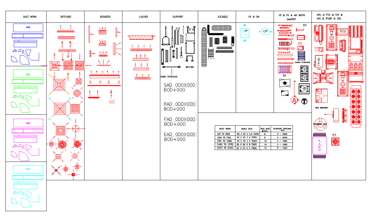
HVAC Duct Legend — Duct Work, Diffusers, Dampers and Equipment Dynamic Blocks
Full HVAC ductwork legend covering supply, return, exhaust and fresh air duct work, diffusers, registers, louvres, flexible connections, supports, the complete damper set and equipment blocks for AHU, FCU, VAV, pumps and fans, with a duct width to angle size…
Screenshots
About
What this drawing shows
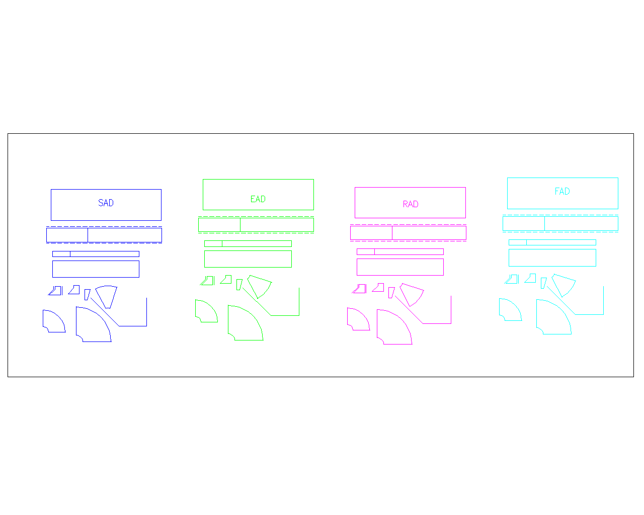
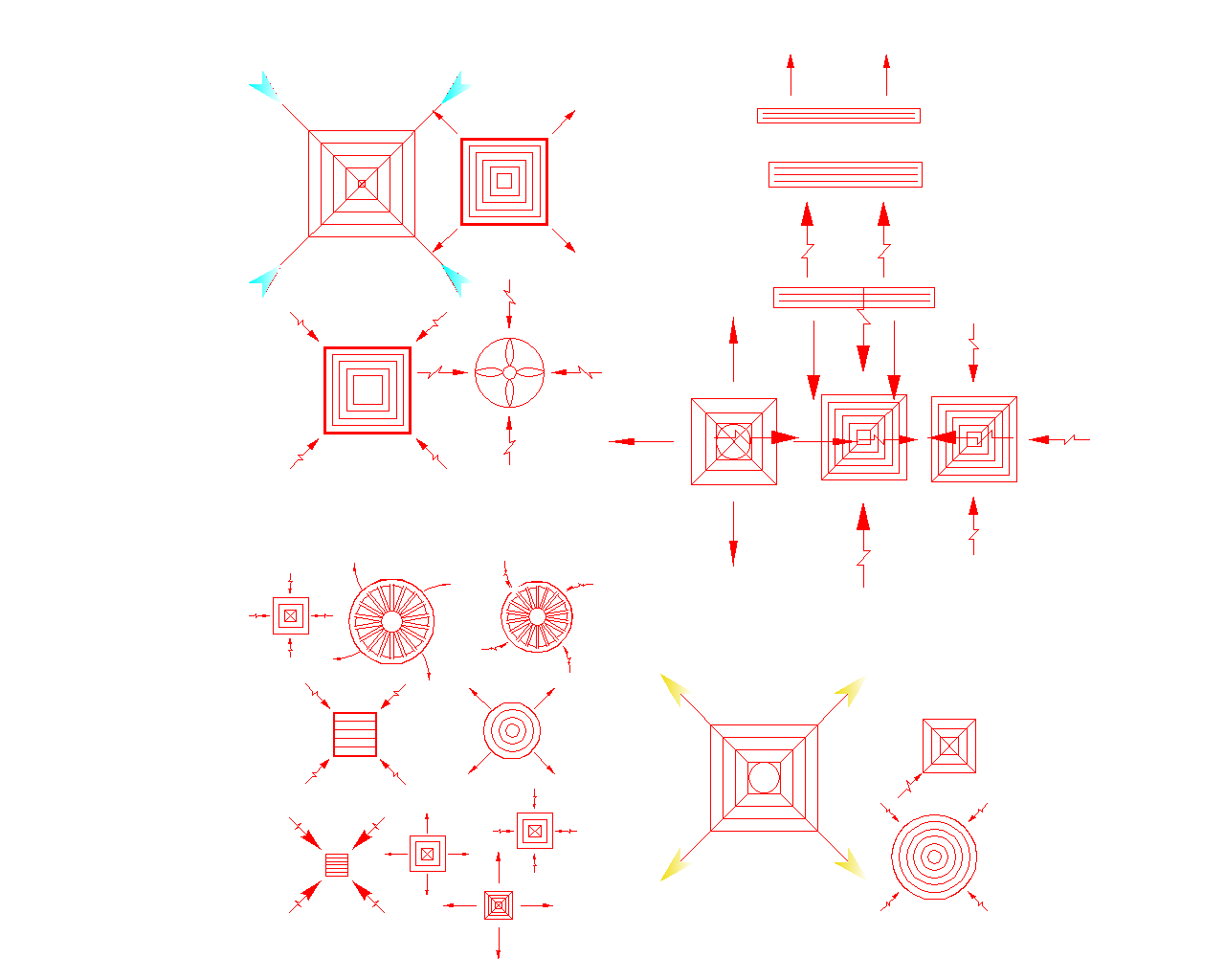
A complete ductwork legend arranged in panels by element type. The duct work panel sets out supply air, return air, exhaust air and fresh air ducts as separate colour-coded entries, each with its rise, drop and transition pieces and its radius and mitred elbows. The diffuser panel holds square and linear diffusers, jet and swirl diffusers, and the one, two, three and four-way throw patterns drawn with directional arrows so the throw is readable on plan without reference to a schedule.
Registers and louvres are given their own panels with supply and return variants. The support panel covers trapeze and rod hangers together with a wall and builder’s opening detail, and carries the duct annotation blocks for supply, return, fresh air and exhaust air ducts, each giving duct size and bottom of duct level. Flexible duct and flexible connector blocks sit alongside, with riser up and down markers in the adjacent panel.
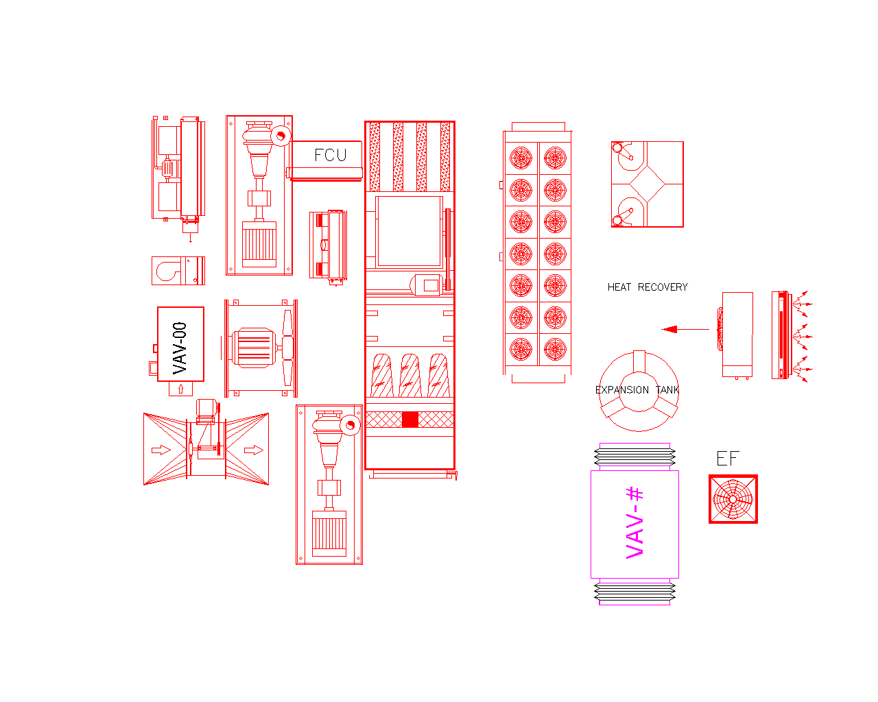
The damper panel is the fullest part of the set — volume damper, fire damper, motorised damper, smoke and pressure dampers, combination fire and smoke damper, sound attenuator and supply air grille, each drawn distinctly rather than as one symbol with different text. The equipment panel covers air handling units, fan coil units, VAV boxes with tags, pumps, fans, exhaust fans, heat recovery units and an expansion tank. A table gives angle iron size against duct width for flanged connections.
All blocks in this file are dynamic. Duct sizes, diffuser throw patterns and equipment configurations are driven from block properties rather than by exploding and redrawing, which keeps the whole set consistent across a drawing set.
Working with dynamic blocks
A dynamic block carries multiple states under a single name, and that has a consequence worth knowing before you build anything on top of this file. A schedule or count extracted from block name alone will treat a 300 × 300 four-way diffuser and a 600 × 600 two-way diffuser as the same item. If you are doing take-off from these blocks, extract the dynamic properties, not just the name, and verify the count against one panel by hand before trusting the whole schedule.
Do not explode them to force a variation. Exploding breaks the link to every other instance and the next global change becomes manual editing across the whole set. If a configuration is missing, add it as a visibility state or lookup parameter in the block editor. Check the annotation behaviour too — text inside a block that is not annotative will not scale with the viewport, and a legend that reads correctly at 1:100 can be unusable at 1:50.
Notes on using the legend
The damper symbols are where accuracy actually matters, and this is the part reviewers check. A volume damper, a fire damper and a combination fire and smoke damper are three different devices with three different approval routes, and they cannot share a symbol with only a text tag to tell them apart. Fire and smoke dampers are life safety devices requiring listed assemblies, access for inspection and testing, and in most cases a documented position on the fire strategy drawings. When a drawing shows a generic damper symbol everywhere and relies on the tag, the count that goes to procurement is wrong and the omission surfaces at commissioning when the dampers cannot be found or accessed. Keep them visually distinct on the plan.
Every fire and smoke damper needs an access panel within reach of it, and the access panel needs to be shown on the drawing rather than left to the ceiling contractor. This is the commonest finding on Civil Defence inspection in the Kingdom — the damper is installed correctly and then sealed permanently behind plasterboard or a fixed ceiling, so it cannot be inspected, reset or tested. Show the panel, size it so a hand and an arm can actually reach the damper linkage, and coordinate its position with the architect’s reflected ceiling plan before the ceiling is set out. NFPA 90A and the Saudi Building Code both address damper installation and access; local Civil Defence requirements may be stricter, so confirm the requirement for your project.
The duct annotation blocks give both size and bottom of duct level, and the level is the field that earns its place. Ductwork is usually the largest service in the ceiling void and it sets the coordination for everything else, so a plan showing sizes without levels pushes the whole clash problem to site. Fill in the BOD at the point the run is drawn. Where ducts cross at different levels, the levels are what let the reviewer check the crossing without a section.
Strip the unused entries before issuing the sheet. A legend showing dampers, louvres and equipment that appear nowhere on the drawings invites questions and suggests the sheet was copied rather than prepared. The reviewer reads a legend as a statement of what is on the drawings.
Angle size table
The table gives angle iron size against duct width for flanged duct connections. Treat it as a starting point and confirm it against the project specification and the duct construction standard governing your work. Flange and reinforcement requirements depend on the duct pressure class as well as the duct dimension, and a table prepared for one pressure class will not suit a higher one. Where the specification calls up a duct construction standard, that standard governs rather than the legend sheet.
Drawing use
- Legend and symbol sheets for HVAC ductwork drawings
- Shop drawings and coordination plans needing a consistent diffuser and damper set
- Reflected ceiling coordination and access panel layouts
Confirm the angle size table against the project specification and duct pressure class before issuing, and remove unused legend entries from the sheet.