 DWG
DWG
Flanged Valves CAD Blocks: Gate, Butterfly, Check Valves, Strainers and Connectors
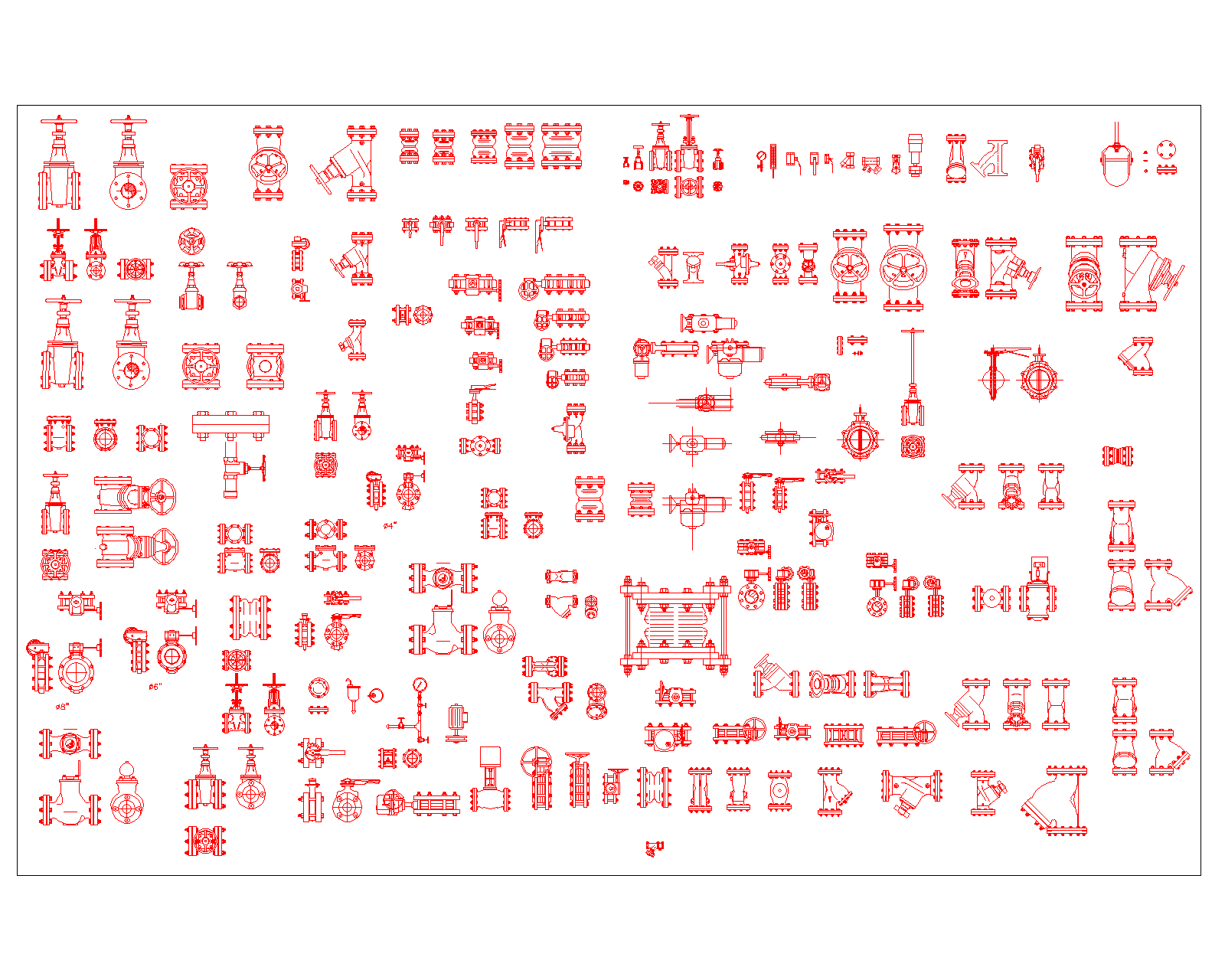
A large DWG library of flanged valves and pipeline fittings in side, end and plan views, covering gate, butterfly, check and globe valves, Y-strainers, flexible connectors and expansion joints.
About
What is in this library
These flanged valves CAD blocks cover most of what you need to draw a pump room, a plant room or a valve chamber without hunting through old projects. The sheet has rising stem gate valves with handwheels in several sizes, butterfly valves with lever and gear operators, swing and wafer check valves, globe and angle valves, Y-strainers, and motorised valves with their actuators. Alongside the valves are single and double sphere rubber flexible connectors, a large bellows expansion joint with tie rods, pressure gauges, small instrument valves and loose flanges.
Most items are drawn in more than one view: a side elevation, an end view showing the flange face and bolt holes, and in many cases a plan. Bolts and nuts are drawn on the flanges, so the blocks hold up in sections and enlarged details, not only on small scale plans. A few blocks carry a nominal size on the sheet, but most do not, so treat them as typical shapes and check sizes before using them in a dimensioned layout.
Check the face-to-face length before you dimension
A valve block on a plan looks exact, but the length between flanges depends on the manufacturer, the pressure class and the standard the valve is made to. Two gate valves of the same nominal size from different makers can differ enough to throw out a tight pump room layout. Once the material submittal is approved, check the face-to-face lengths in the approved data sheets against the blocks and stretch or redraw where they differ, before the shop drawing goes out with dimensions on it.
Flange drilling is the same story. Projects often mix ASME class flanges on imported equipment with PN flanges on locally supplied pipe and valves, and the bolt patterns do not always match. The end views in this library are handy for spotting that early: lay the valve end view over the pump or equipment flange and the mismatch is obvious.
Using these flanged valves CAD blocks on site layouts
Leave room for the parts that move. A rising stem gate valve needs clear height above it for the stem when the valve is fully open, and a gear operator needs its handwheel on the side where someone can actually stand and turn it. On crowded headers it is easy to end up with handwheels facing a wall or stacked so close together that only one can be turned at a time.
Watch what is bolted directly to a butterfly valve. When a wafer or lug butterfly valve opens, its disc swings out past the body on both sides. Bolt it straight onto a wafer check valve, a reducer or a strainer and the disc can hit the next item and refuse to open fully. Put a short spool piece between them on the drawing, so the fitter does not discover it on site.
Strainers need space to be cleaned. The basket or screen on a Y-strainer comes out through the cap, and the cap needs clearance and a drain point under it. Flexible connectors and expansion joints need anchors and guides on the pipe either side, otherwise the pipe moves instead of the connector, and the tie rods on the bellows joint should be shown as they will be installed.
For fire protection work, use these blocks for layout and coordination, then replace the valve tags and notes with the approved make and model. Valves on fire water service need to be listed or approved for that use, and control valves on the water supply need supervision, so the shop drawing has to show the supervisory switch where one is fitted.
Counting valves for the takeoff
If each valve type is kept as a named block, you can count them per drawing with QSELECT, BCOUNT or a data extraction table instead of counting off a print. Give each block a clear name with its type and size, such as gate valve 150 or butterfly gear 200, and the takeoff becomes a matter of exporting a table.
File details
- Format: DWG
- Views: side elevation, end view and plan for most items
- Gate, butterfly, check, globe and motorised valves, Y-strainers, flexible connectors, expansion joint and gauges
- Most blocks are typical shapes without fixed sizes; scale and check against the approved data sheets