 DWG
DWG
PVC and Cast Iron Drainage Fittings — Dynamic CAD Block Library
Drainage fitting library in DWG covering PVC bends, tees, wyes, reducers, branch types, traps and cleanouts in plan and isometric, with cast iron and PVC fixture blocks, floor and vertical drains, a pipe riser set and an inspection chamber detail.…
Screenshots
About
What this drawing shows
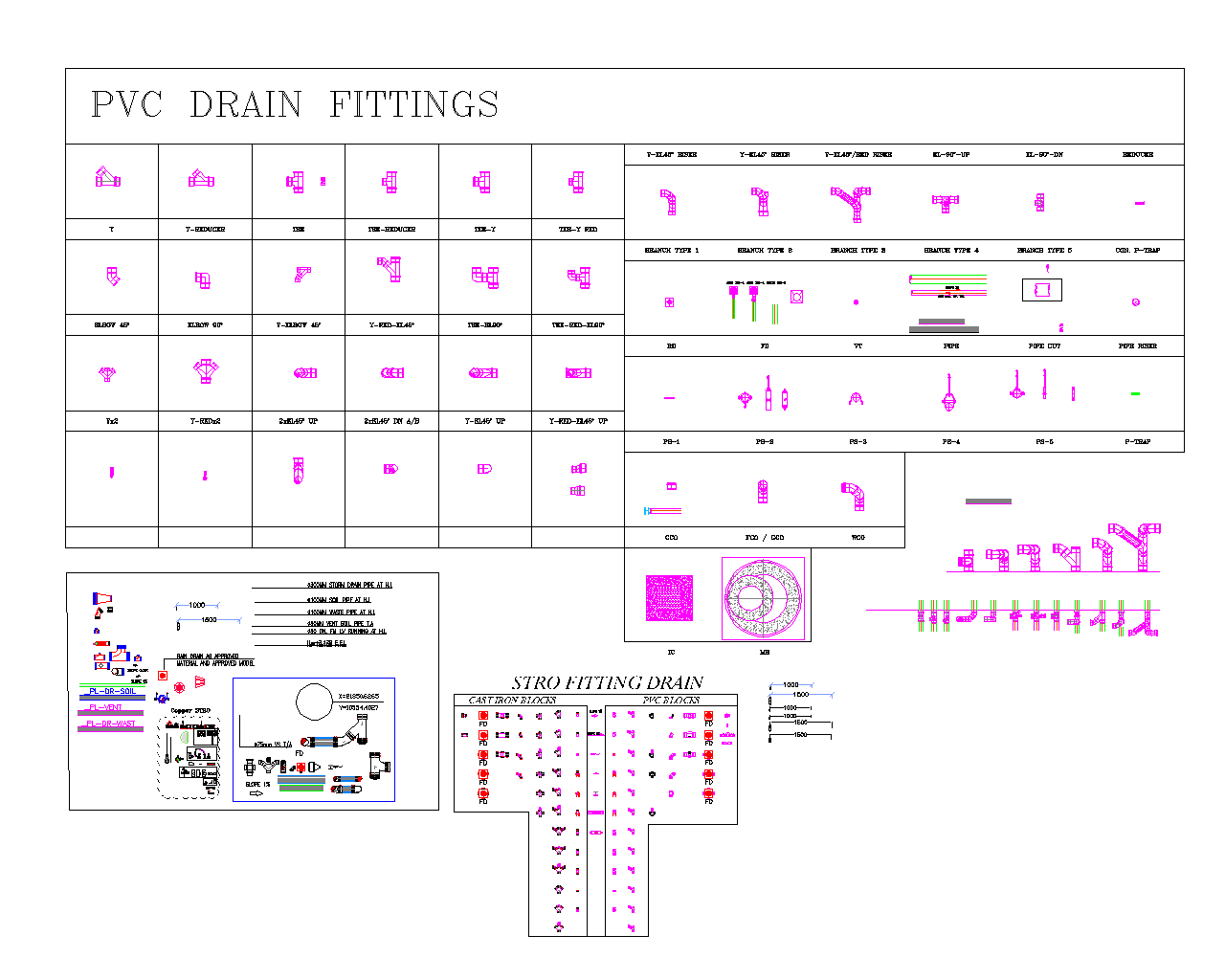
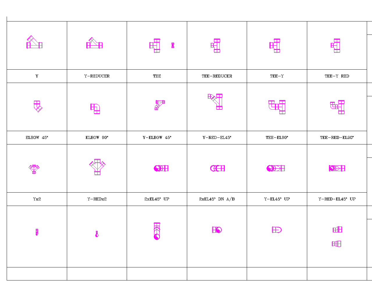
A drainage fitting library arranged as a labelled matrix. The main table covers wye and wye-reducer fittings, tees, tee-reducers, tee-wye and tee-wye reduced patterns, 45° and 90° elbows, wye-elbow and reduced wye-elbow combinations, tee-elbow and tee-reduced-elbow assemblies, double wye and double reduced wye fittings, and the paired 45° elbow arrangements used to offset a stack. Each is drawn as a named block so the fitting can be identified from the drawing without reference to a schedule.
A second table holds riser fittings — wye-elbow risers, wye-elbow with reduced riser, 90° elbows up and down, reducers, five branch connection types, and P-trap connections. Below that are the drain and vent markers: floor drain, floor cleanout, vent terminal, pipe, pipe cut and pipe riser symbols, plumbing fixture blocks, and P-trap variants. Cleanout blocks cover floor cleanout, floor cleanout with grease cover and wall cleanout.
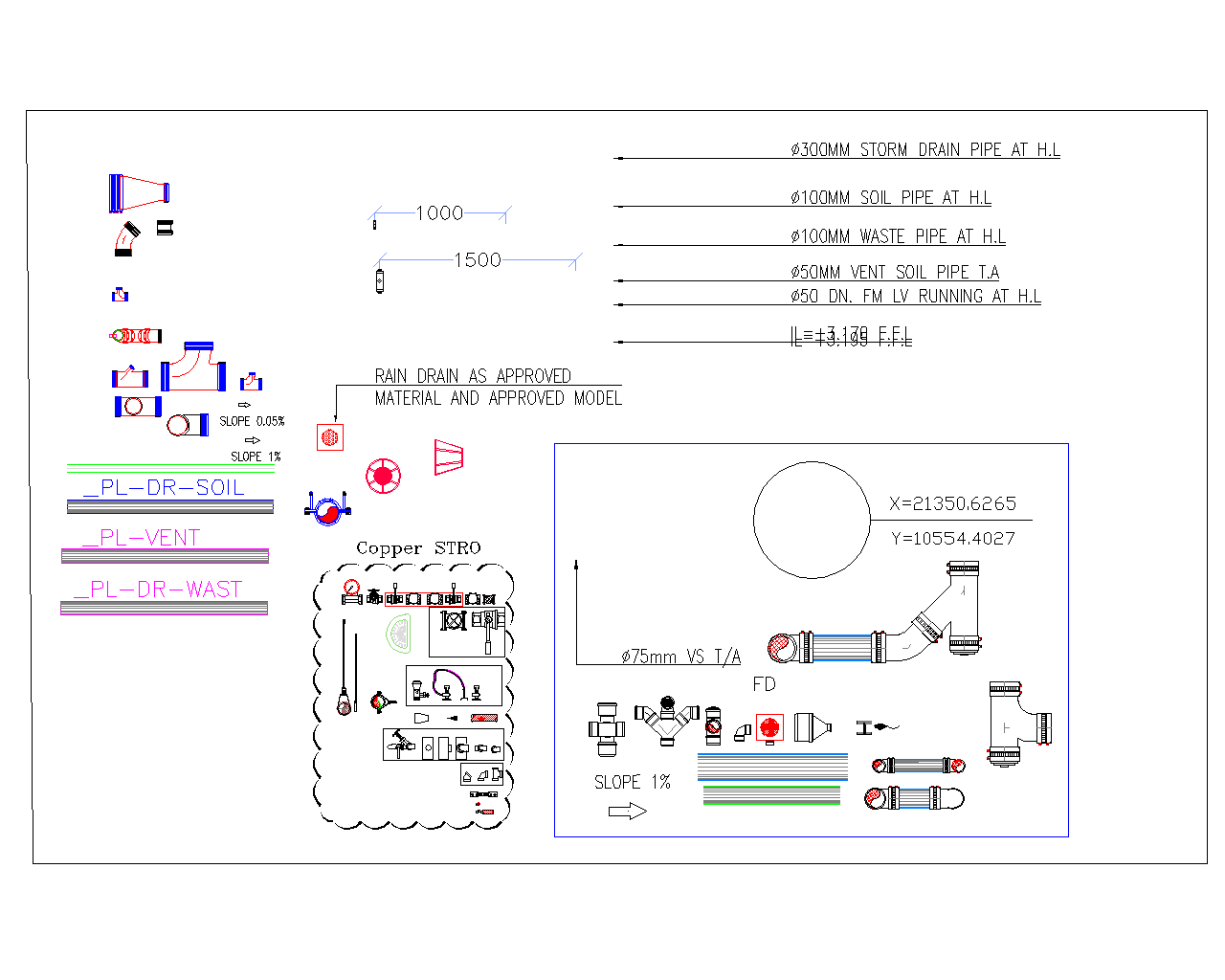
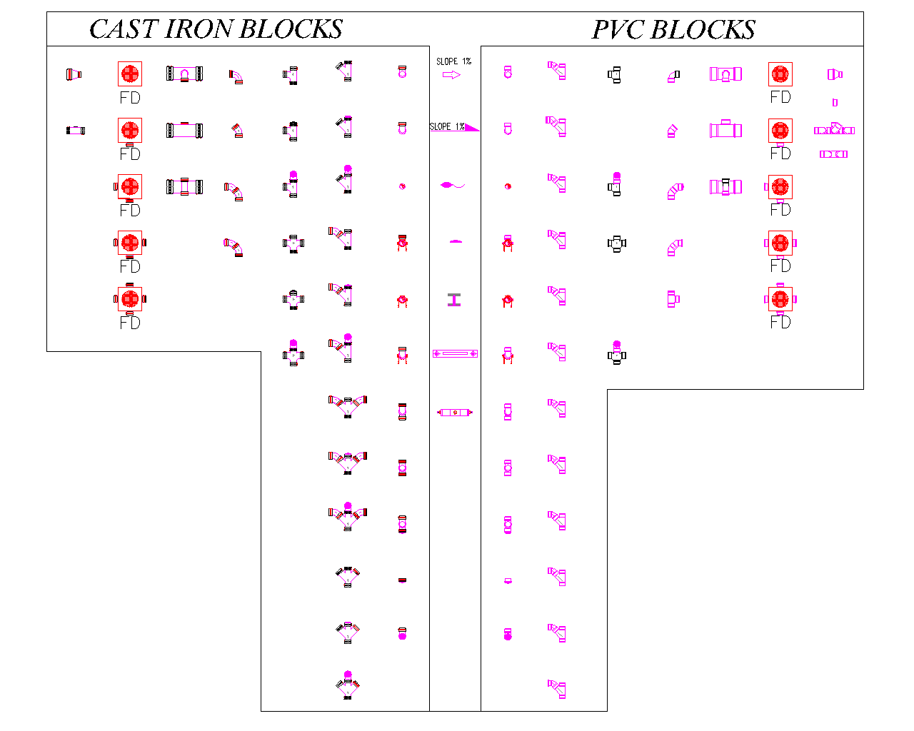
The lower panels carry a pipe riser diagram with soil, waste, vent and storm lines set out at level with their layer names and a slope note, an inspection chamber and manhole detail, and a fixture block panel giving matched cast iron and PVC sets for floor drains and connection points. An isometric fitting group sits at the right for use in riser and single-line isometric drawings.
All blocks in this file are dynamic. Fitting sizes and orientations are driven from block properties rather than by exploding and redrawing, which keeps the whole set consistent across a drawing.
Working with dynamic blocks
A dynamic block carries several states under a single name, and that matters before you build a schedule on this file. A take-off extracted from block name alone will treat a 50 mm wye and a 100 mm wye as the same item. Extract the dynamic properties, not just the name, and check the count against one table by hand before trusting the whole schedule.
Do not explode a block to force a variation. Exploding breaks the link to every other instance and the next global size change becomes manual editing. If a fitting configuration is missing, add it as a visibility state or lookup parameter in the block editor instead.
Installation notes
The distinction between fitting types in this library is not cosmetic, and drawing the wrong one is the commonest way a drainage layout fails review. A sanitary tee and a wye are not interchangeable. A sanitary tee is for connecting a horizontal branch into a vertical stack; used flat on a horizontal run it obstructs flow, catches solids and blocks. Horizontal-to-horizontal and horizontal-to-vertical connections take a wye with a 45° elbow, or a combination wye and eighth bend. Site fitters who are used to running conduit will reach for the tee because it is shorter, and the plumbing code prohibits it — check both the drawing and what is actually installed. The same logic applies to the double fittings here: a double sanitary tee on a horizontal run allows discharge from one branch to cross into the other, and the code restricts where it may be used.
Every trap needs venting, and the vent has to be within the distance from the trap that the code permits for that trap arm size. Beyond that distance the trap seal siphons out and the fixture passes drain gases into the room, which is a defect that only shows up in use. The permitted trap-to-vent distance varies with pipe diameter and with the code edition enforced on your project, so take the figure from the governing code rather than a standard detail. The riser diagram on this sheet shows soil, waste and vent as separate systems and it is worth keeping them separate in the layer structure too, because a printed submittal without colour still has to show which line is which.
Cleanouts are drawn on this sheet and they are the item most often value-engineered off the drawing and then missed. A cleanout is needed at the base of every stack, at changes of direction beyond what the code allows without access, and at intervals along long horizontal runs; the interval and the direction-change allowance both come from the governing code. What matters more on site is that the cleanout ends up reachable. A floor cleanout tiled over, buried under a fixed unit or terminated behind finished joinery is the same as having none, and the first blockage proves it. Show the cleanout position on the drawing, coordinate it with the architect’s floor finishes, and confirm the cover type suits the finish — a plain cover in a food preparation area or a car park is the wrong specification.
On slope, the riser diagram here carries a slope note. Confirm it against the project specification and the governing code, because minimum fall varies with pipe diameter and a single figure applied across all sizes is wrong in both directions. Too flat and solids are left behind; too steep and the liquid runs away from the solids, which blocks just as reliably and is the failure people do not expect. Where a drainage pipe penetrates a fire rated slab or wall, PVC is combustible and needs a listed firestop system, usually an intumescent collar sized for the pipe — mineral wool and sealant is not a rated penetration. Saudi Civil Defence requirements may be stricter than the referenced standard, so confirm the requirement for your project before the penetrations are cast.
Drawing use
- Drainage layouts, riser diagrams and single-line isometrics
- Shop drawings and coordination plans for soil, waste, vent and storm systems
- Fixture connection details and cleanout schedules
Confirm slope, trap-to-vent distance and cleanout spacing against the code governing your project before issuing. Fitting selection shown here is a library, not a design.