 DWG
DWG
Platform Trolley CAD Block: Top, Side and Front View
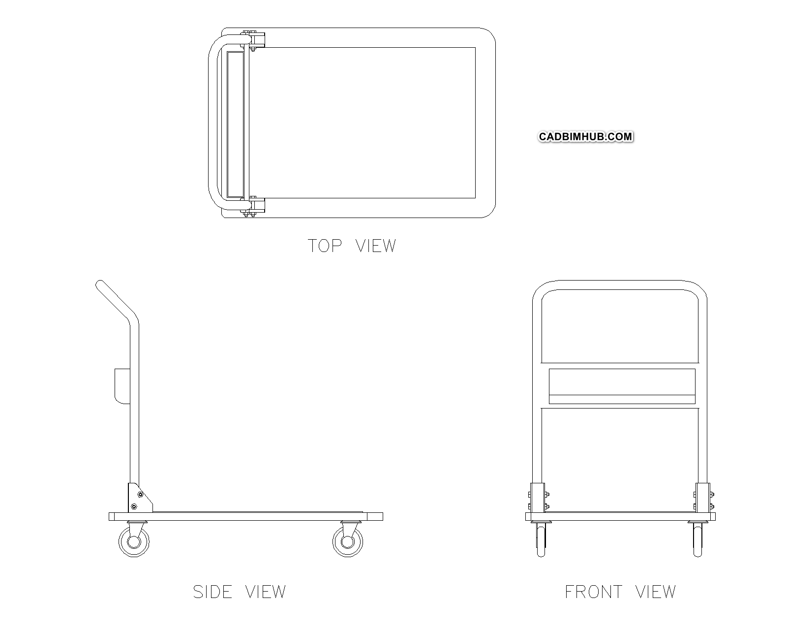
A platform trolley with a flat deck, four castors and a hinged push handle, drawn in top view, side view and front view as three separate blocks.
About
What this drawing shows
This platform trolley CAD block, also called a platform hand truck or flatbed trolley, is drawn in three views. The top view shows the rectangular deck with its rounded corners and the push handle at one end, held in a pair of hinge brackets. The side view shows the handle rising from its bracket and bending back at the top, the pins at the base of the handle, the deck edge and the castors on their forks. The front view looks at the trolley from the handle end, with the handle frame, its cross panel and the castors seen end on.
The trolley measures about 806 mm long including the handle, 532 mm wide and 774 mm high to the top of the handle. Each view is its own block, so you can insert just the plan on a layout and keep the elevations for sections or room elevations.
File details
- Format: DWG, saved as AutoCAD 2004, so it opens in any later version
- Units: millimetres, drawn at 1:1
- Three blocks: top view, side view and front view
- Geometry is plain lines on a single layer, which keeps the file small
Drafting notes
Most people drop a trolley on a plan to make the room look furnished, but its real job is checking a route. Put it on the plan with the handle and a person behind it, and walk it from the loading bay to wherever it has to go. Straight corridors are rarely the problem. The trouble is at corridor corners, at doors that open into the route, and at lift cars where the trolley and the person pushing it have to fit inside together with the doors closed.
When you check a doorway, measure the clear opening from the face of the open leaf to the stop on the other side, not the structural opening. A door that looks wide enough on the architectural plan loses a good part of its width to the leaf thickness, the hinge side and any closer arm or hold-open device. Double doors with one fixed leaf catch people out the same way, because only one leaf opens in daily use.
Floors matter as much as walls. Castors catch on threshold strips, expansion joint covers and the edges of floor drain channels, and a loaded trolley dropping a wheel into a channel grating is a common complaint in kitchens and service corridors. If a drainage channel or floor gully sits in the trolley route, the grating needs to be rated for wheeled loads, and it is better to move it out of the route at design stage than to argue about it at handover.
In plant rooms the same check is often skipped. Filters, small motors, valves and boxed spares all come in on a trolley, and the route from the door to the equipment gets blocked by things drawn at low level by different trades: a drain line run across the floor, a pipe support base, the edge of a housekeeping pad or a cable tray dropping to a panel. On a coordinated shop drawing, keep a clear path from the plant room door to every item that will need replacing, and use this block to prove it.
Using the platform trolley CAD block
Insert at a scale of 1 in a millimetre drawing. If your drawing is set up in metres, insert at 0.001. The curves are made of short straight segments, so the block stretches badly; if you need a larger or smaller deck, redraw the outline rather than exploding and scaling it in one direction. On architectural plans it is worth putting the trolley on a non-plotting or equipment layer so it can be switched off before issue.
For room elevations and sections, use the side view. Its base point sits at floor level in the middle of the trolley, so it snaps straight onto the finished floor line and you can show it parked against a wall, under a worktop or inside a lift car without moving it up or down afterwards.