 DWG
DWG
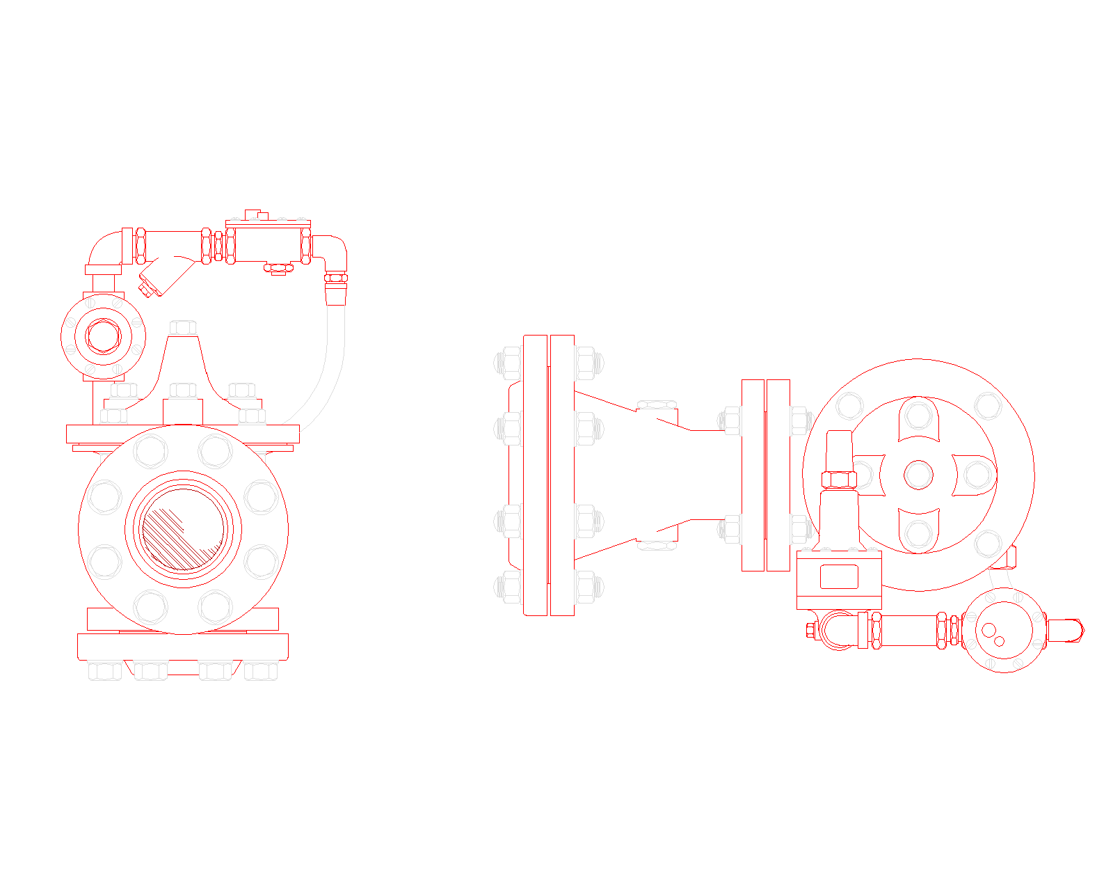
Fire Pump Pressure Relief Valve with Waste Cone: Top and Front View
Pilot-operated pressure relief valve for a fire pump discharge, drawn in top view and front view with its pilot trim and a flanged waste cone on the outlet.
About
What this drawing shows
This pressure relief valve with waste cone is drawn the way it sits in a fire pump room, in top view and front view. The front view looks at the inlet flange of the valve, with the pilot trim running over the top: an elbow off the inlet side, a Y-strainer, unions either side of the pilot control and tubing that drops back to the main valve cover. The top view shows the valve body from above with the pilot beside it, and the outlet flange bolted to a waste cone that opens out to a larger flange on the discharge side. The label on the drawing gives the valve as 3 inch with a 6 inch cone outlet.
All the bolts, nuts and flange faces are drawn, so the block can go straight into a pump room layout or a section without adding detail.
Why the waste cone is there
A main relief valve on a fire pump only opens when discharge pressure climbs past its set point. When it does, someone in the pump room needs to see it. The waste cone gives an air break between the valve outlet and the drain line, so the flow is visible during the weekly run and during the annual test, and it widens the outlet so the water slows down before it goes into the discharge pipe. A relief valve dumping water into a closed pipe with nothing to show it is flowing can run for months without anybody noticing, wasting water and hiding a pump that is running at a higher pressure than it should.
Where a pressure relief valve with waste cone is used
NFPA 20 limits where a main pressure relief valve may be used. It is mainly a diesel driven pump item, because engine speed can rise above rated and push the pressure up with it. Where a diesel pump’s shutoff pressure plus the maximum static suction pressure goes above the rating of the system components, the standard calls for one. On a constant speed electric pump it is not meant to cover for a pump that was selected too large; the fix there is the right pump. Do not confuse it with the casing relief valve, the small valve on the pump casing that lets a trickle of water through to stop the pump overheating at churn. The two do different jobs and both can appear on the same drawing.
Site and drafting notes
Think about where the water goes before you place the block. A relief valve can pass a large flow, and a pump room floor drain sized for a leaking gland will not keep up with it. On most projects it is easier to run the discharge from the waste cone back to the fire water tank, where the pump room sits next to it, than to size a drain and sump for the full flow. Check the discharge pipe size against NFPA 20, and remember that extra elbows on a long discharge run push the pipe up a size.
Leave room around the pilot trim. The Y-strainer screen has to come out for cleaning, and the pilot has to be adjusted when the set pressure is fixed during the acceptance test. On congested layouts the valve often ends up with its trim facing a wall or tucked under the discharge header, which looks fine on plan and makes the first service visit a misery. The top view in this block is the quickest way to check that clearance against the walls and the other pipework.
Keep the flow direction clear on the drawing and on site. The valve is not symmetrical, and a pilot-operated valve fitted the wrong way round will not relieve. Put a flow arrow on the shop drawing next to the block, and match the valve orientation to the manufacturer’s installation sheet for the model you are using, because pilot arrangements differ between makers.
Finally, record the set pressure. Write it on the shop drawing, in the test report and on a tag at the valve. The next person to touch the pilot should know what it was set to and why.
File details
- Format: DWG
- Views: top view and front view
- Includes pilot trim with Y-strainer, unions and tubing
- Flanged waste cone on the valve outlet