 DWG
DWG
Fire Pump Set CAD Blocks — Diesel, Electric and Jockey Pump Plan and Elevation
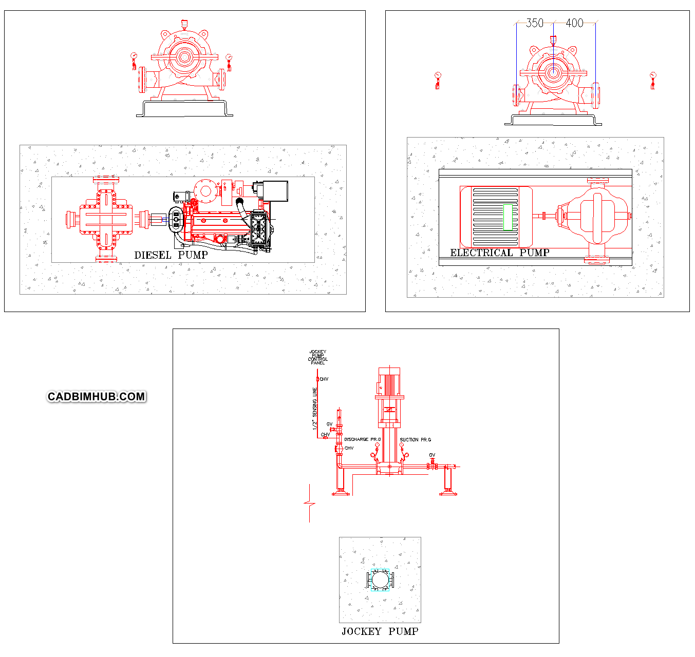
Fire pump set drawn in plan and end elevation: a diesel engine driven horizontal split case pump, an electric motor driven horizontal split case pump, and a vertical multistage jockey pump with its suction, discharge and pressure sensing line piping,…
About
What this drawing shows
The three pumps of a typical fire pump set, each drawn on its concrete plinth. The diesel fire pump is shown in plan as a horizontal split case pump coupled to its engine, with the end elevation of the pump casing above showing the suction and discharge flanges and the suction and discharge pressure gauges. The electric fire pump is shown the same way — horizontal split case pump and motor on a common baseplate in plan, with the end elevation dimensioned above.
The jockey pump is a vertical multistage pump shown in elevation with its suction and discharge pipework, gate valves, check valve, suction and discharge pressure gauges, and the pressure sensing line running up to the jockey pump controller with its check valves. A plan of the jockey pump on its plinth sits below. Together the three blocks cover the equipment layout of a pump room for a sprinkler, standpipe or hydrant system.
Installation notes
On a horizontal split case pump, the suction pipework causes more problems than the pump. NFPA 20 prohibits an elbow in the suction line within a set number of pipe diameters of the suction flange where the elbow’s plane is parallel to the pump shaft, because it loads one side of the double-suction impeller more than the other and wears the bearings. Reducers on the suction side must be eccentric, flat side up, so that no air pocket forms at the top of the pipe. And NFPA 20 restricts butterfly valves on the suction side close to the pump for the same flow-disturbance reason; an OS&Y gate valve is the usual answer. All three of these are routinely wrong on site because the fabricator lays the suction header out to fit the room rather than the pump, and they cannot be fixed after the room is finished without cutting the header out. Take the distances from the edition of NFPA 20 enforced on your project and put them on the drawing.
Alignment between pump and driver is checked at the factory and lost in transit, so it has to be checked again after the baseplate is grouted and again after the pipework is connected. Pipework that is pulled onto the pump flanges to make it fit puts the casing under strain and moves the alignment out, which shows up as coupling wear and vibration within months. Support the suction and discharge pipework independently so that the pump carries none of its weight, and make the final flange connection without forcing it. On the diesel pump, the pump room needs combustion and cooling air for the engine, the exhaust must discharge well away from openings and air intakes, and the fuel tank, batteries and room temperature all have requirements under NFPA 20. In a Riyadh summer the pump room ventilation is the item most often undersized, and a diesel engine that overheats during its weekly run is the first sign.
The jockey pump is not a fire pump. It keeps the system pressurised against small leakage so that the main pump does not start for every pressure drop, and it should be sized for that leakage, not to supply sprinklers. A jockey pump sized too large will hold pressure during a real fire flow long enough to delay the main pump starting. Its start and stop pressures, and the main pumps’ start pressures, are staggered so that the jockey starts first, then the electric pump, then the diesel — set them from the system design and record them on the controller door. A jockey pump that cycles every few minutes is not a controller fault; it is telling you the system is leaking.
Each pump has its own pressure sensing line, as the jockey pump detail shows, connected between the pump’s discharge check valve and its control valve. NFPA 20 sets the material and the check valve arrangement in the sensing line, including the drilled clappers that allow the controller to be tested, and a shared sensing line or one taken from the wrong side of the check valve means the controllers respond to the wrong pressure. Saudi Civil Defence requirements for pump room location, fire separation, controller type and testing may be stricter than the referenced standard, so confirm them before the pump room layout is fixed.
Drawing use
- Pump room layouts and equipment arrangement drawings
- Civil Defence submittals for fire pump installations
- Coordination drawings for plinths, pipework and access around pumps
Replace these blocks with the certified dimensions of the selected pumps and drivers before issuing, and confirm suction pipework and sensing line arrangements against NFPA 20.