 DWG
DWG
Pendent Sprinkler CAD Block: Plan Symbol for End and Inline Heads
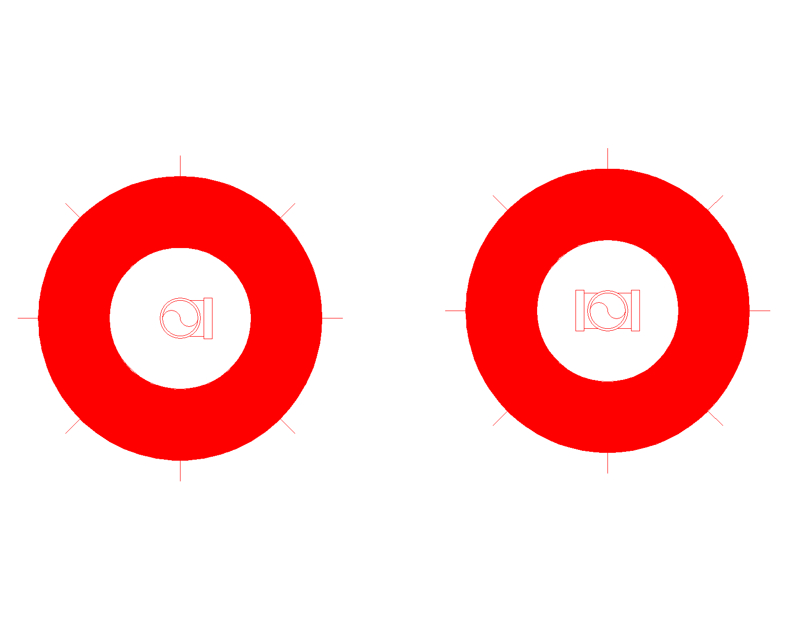
Plan view symbols for a pendent sprinkler, one fed from a single side at the end of an arm and one fed from both sides on a tee, ready to drop onto sprinkler shop drawings.
About
What this drawing shows
This pendent sprinkler CAD block gives you the plan view symbol of a pendent head in two versions. Both have the same outer ring with eight short tick lines around it and the sprinkler head drawn at the centre. The difference is the pipe connection. In the left symbol the pipe joins the head from one side only, the way a head sits at the end of an arm-over or on an elbow at the end of a branch. In the right symbol the pipe runs in from both sides, the way a head sits on a tee in the middle of a branch line.
Keeping the two versions separate matters more than it looks. The installer reading the plan can see straight away which heads take a tee and which take an elbow or a reducing coupling, and the fittings on the takeoff come out right without someone going back through every branch by hand.
The ring is a symbol, not a coverage area
New draughtsmen sometimes read the red ring as the area the head protects. It is not. NFPA 13 works out the protection area of a sprinkler as the spacing along the branch line multiplied by the spacing between branch lines, which gives a rectangle, and the maximum figures depend on the hazard classification and the type of sprinkler. If you need to show coverage on a layout for a design check, draw the spacing grid separately on its own layer and keep this block for the head position only.
Using the pendent sprinkler CAD block on shop drawings
The ring is a solid fill, so on a busy shop drawing it can sit on top of the branch line and hide the pipe. Send the sprinkler blocks behind the pipework with DRAWORDER, or put them on a layer you can screen when plotting, so both the heads and the pipe sizes stay readable on the printed sheet.
Insert the block at the actual head position, not where it looks tidy on the plan. Pendent heads sit below the ceiling, so their positions have to be checked against the reflected ceiling plan before the shop drawing goes for approval. In a grid ceiling the consultant will usually want each head in the centre of a tile, and the heads have to stay clear of light fittings, diffusers and other ceiling items that would block the spray pattern. These clashes are far cheaper to fix on the drawing than after the ceiling grid is up and the drop nipples have been cut.
Watch the drop length as well. Where the ceiling level changes, at bulkheads, soffits or around a raised ceiling, the same branch line can feed heads at two or three different levels, and each one needs its own drop. Mark those heads on the plan with a note or a level tag, because the symbol alone looks the same at every height.
Counting heads for the takeoff
Because the end and inline versions are separate blocks, you can count them directly with QSELECT, BCOUNT or a data extraction table instead of counting heads off a printed plan. The count of end heads gives you the elbows or reducing couplings, the count of inline heads gives you the tees, and the total gives you heads, escutcheons and spare heads for the cabinet. Run the count per floor or per zone, so the takeoff can be checked against each zone control valve.
If the project uses recessed or concealed pendent heads in some areas, note it in the legend or use a separate block name for them. The plan symbol is the same, but the head, the escutcheon or cover plate and the price are not, and a single block name for all of them will throw the takeoff off.
File details
- Format: DWG
- View: plan
- Two symbols: pendent sprinkler fed from one side, and pendent sprinkler fed from both sides
- Use it with your own sprinkler legend and layer standard