 DWG
DWG
2-Way Fire Department Connection Installation Detail — DWG
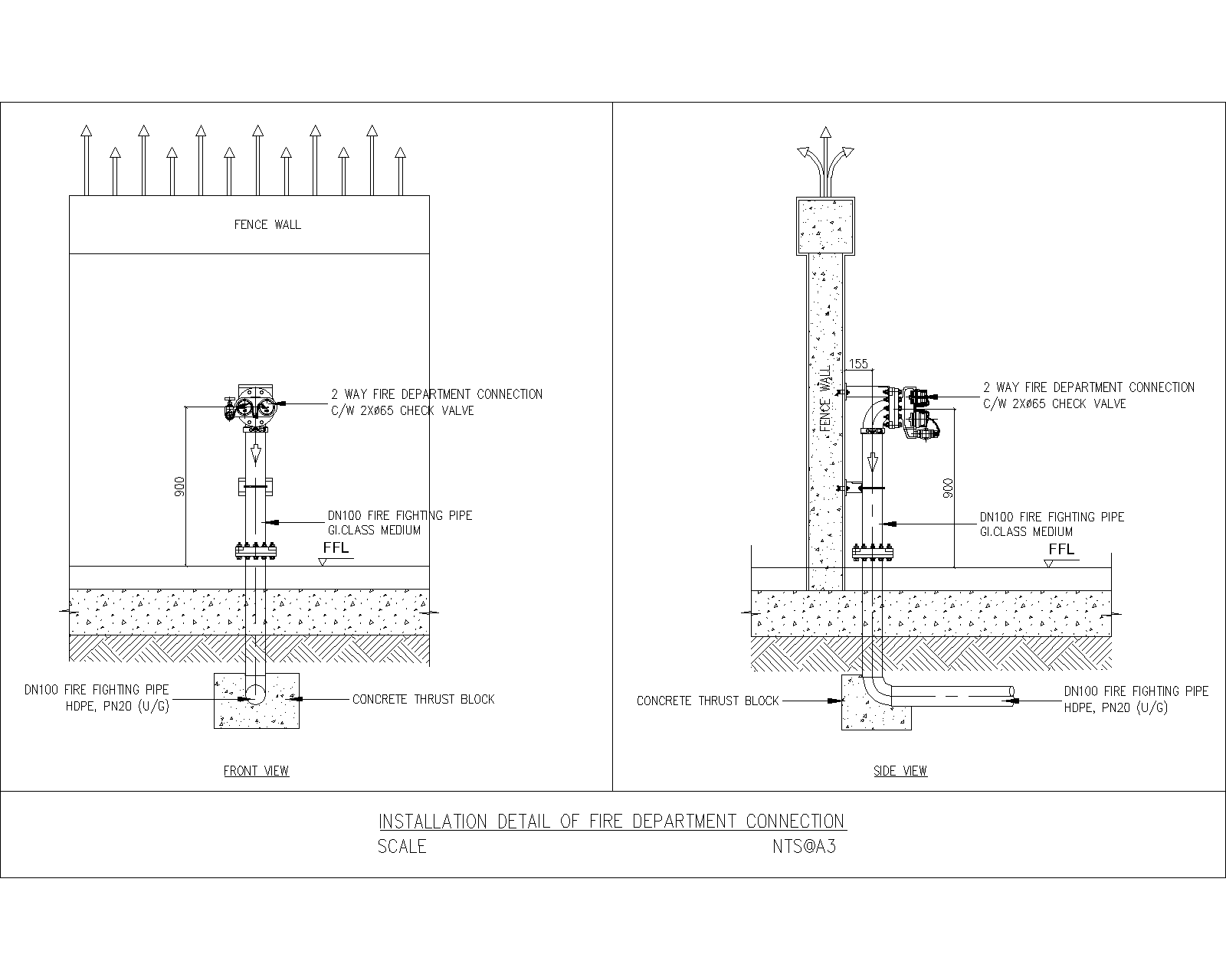
Free-standing 2-way fire department connection detail in front and side view, showing 2×Ø65 check valves, DN100 GI riser, HDPE PN20 underground transition and concrete thrust block.
About
A free-standing fire department connection mounted at a fence wall, drawn in front and side view. The detail covers the inlet arrangement, the transition from underground HDPE to above-ground galvanised pipe, and the thrust block that restrains it.
What the detail shows
- 2-way FDC with 2 × Ø65 check valves
- DN100 fire fighting pipe, GI Class Medium above ground
- DN100 HDPE PN20 underground with elbow transition
- Concrete thrust block at the bend
- 900 mm from FFL to FDC centreline
- 155 mm projection from the fence wall face
- Flanged connection and pipe support arrangement
Installation notes
The 900 mm mounting height sits within the range NFPA 14 allows for a free-standing connection. Confirm the figure against your local authority before issuing — Civil Defence requirements vary across the Gulf.
The thrust block matters more than it looks. The 90° bend where HDPE turns up carries the full thrust of the line at working pressure, and an unrestrained bend will walk under surge. Size it against the pipe diameter and test pressure rather than copying the block shown.
The HDPE to GI transition is placed below finished floor level so that no plastic pipe is exposed above grade, which most authorities require.
Check that the Ø65 inlet threads match what the attending fire department carries. Thread standards are not consistent between jurisdictions and a mismatch is only discovered when it is needed.
Keep the connection clear of parked vehicles and landscaping. The clearance is a code requirement in most jurisdictions, and it is the item most often failed at inspection.
Applicable standards
- NFPA 14 — Standpipe and Hose Systems
- Check local Civil Defence requirements for inlet type, height and signage