 DWG
DWG
Fire Fighting Shop Drawing Details — Valves, Sprinklers, Hydrant and Pipe Supports
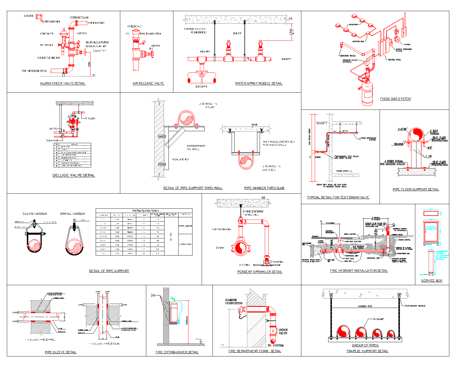
Seventeen fire fighting details on one sheet covering alarm check, deluge and air release valves, water spray nozzle, FM-200 clean agent system, pendent sprinkler, test drain, fire department connection, hydrant, extinguisher mounting, pipe sleeves and wall, slab, floor, clevis, swivel…
Screenshots
About
What this drawing shows
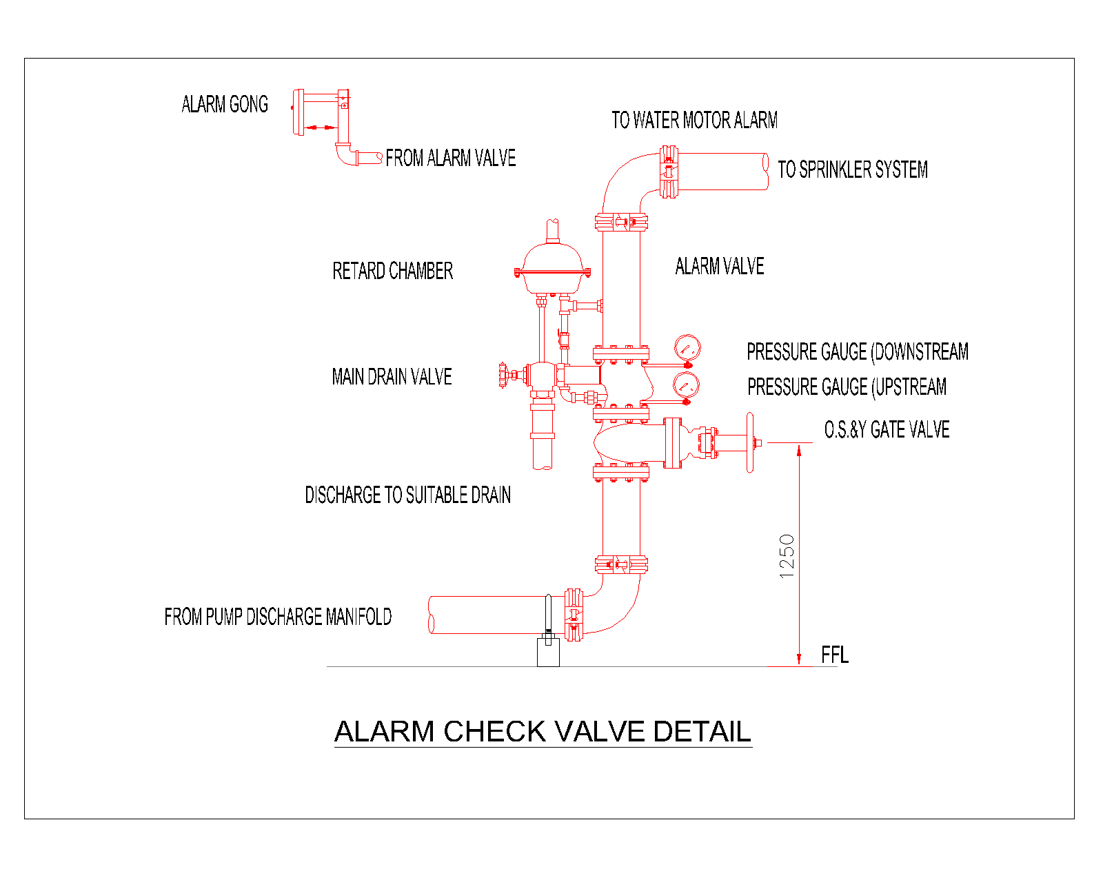
A single sheet of seventeen typical details for fire fighting shop drawings. The valve details cover the alarm check valve trim with retard chamber, water motor gong connection, pressure gauges and main drain, the deluge valve with its trim and a legend of components, and an air release valve assembly with isolation valve. System details include a water spray nozzle arrangement fed from a riser with hangers to the slab, an isometric of an FM-200 clean agent system showing detectors, discharge nozzles, control panel, manual release, pressure switch and cylinder, a pendent sprinkler drop from the branch line, and a typical inspector’s test and drain arrangement at a shaft with combined test and drain valve and sight glass.
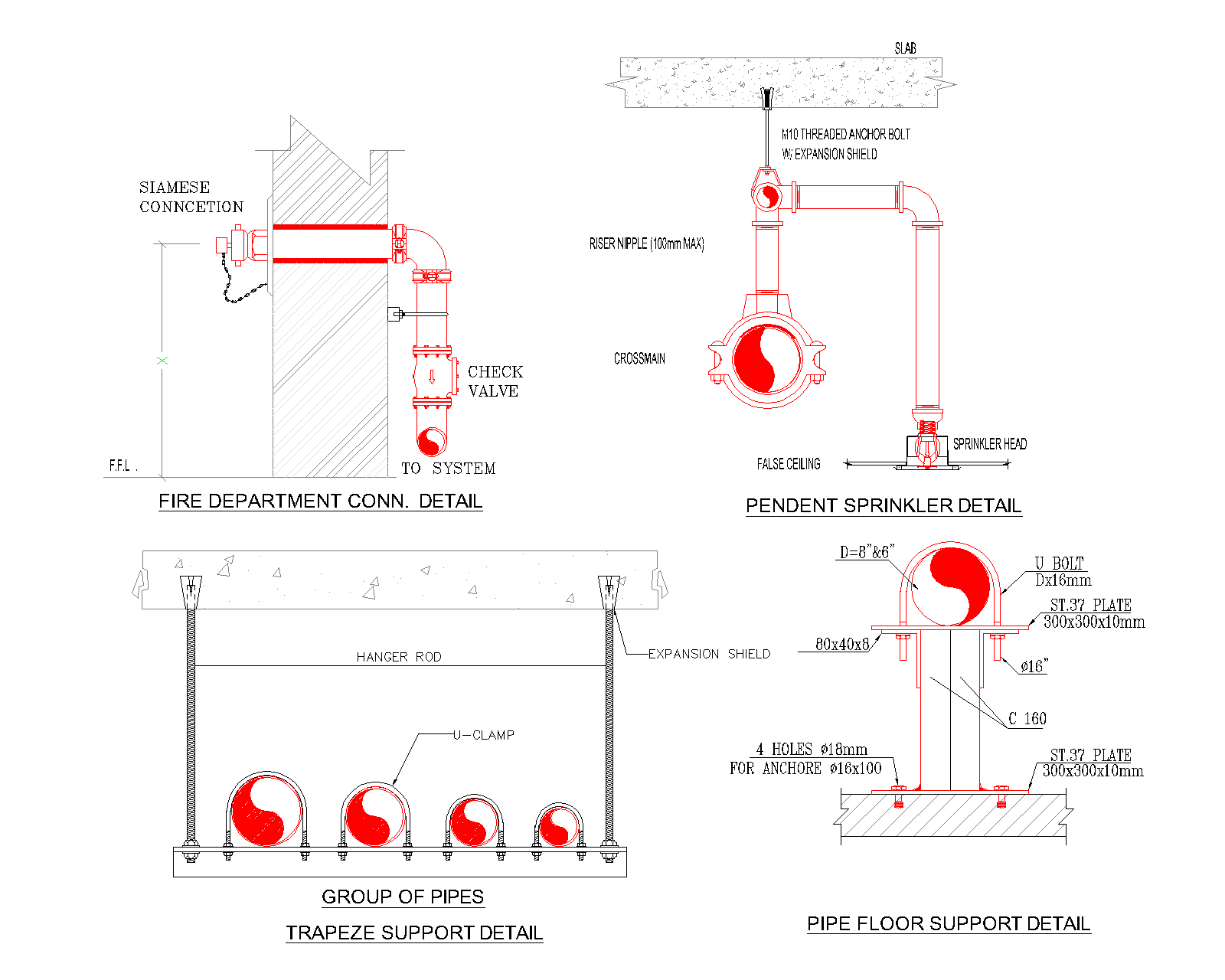
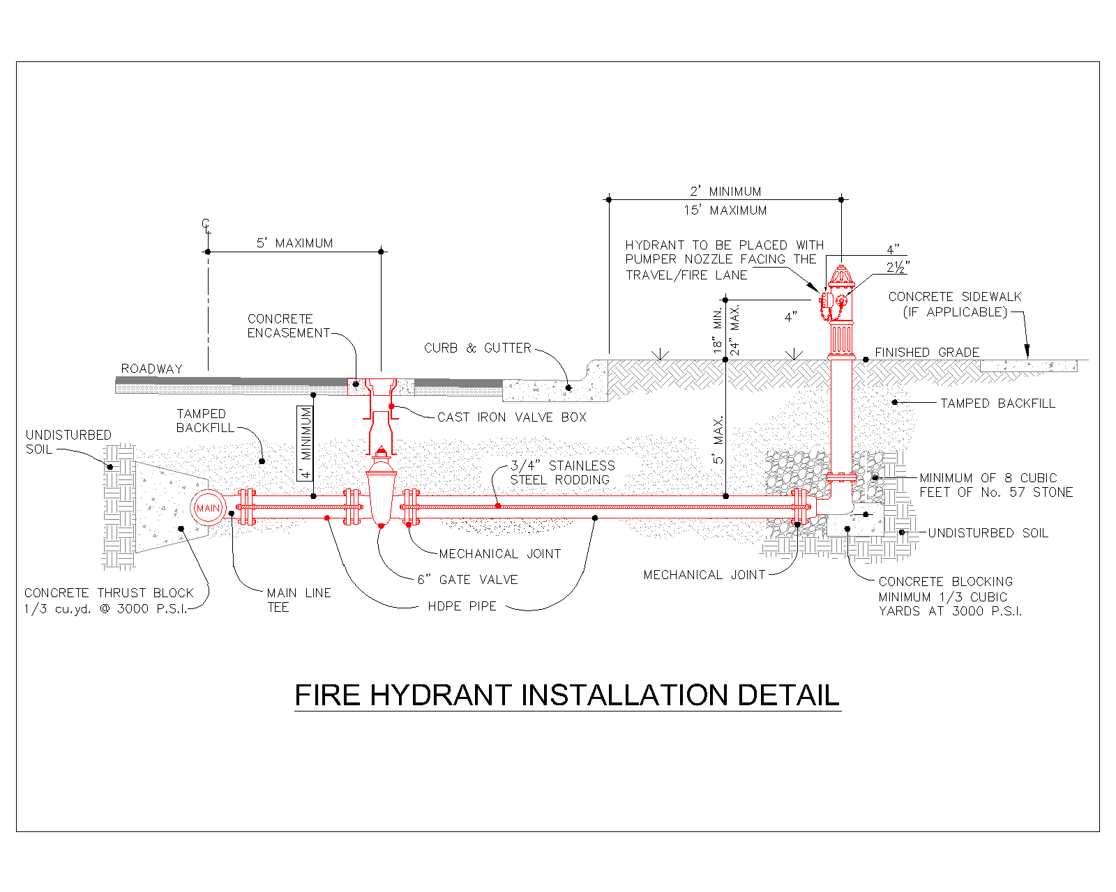
External and terminal details cover the fire department (Siamese) connection through the wall with check valve, a fire hydrant installation in section with thrust blocking, valve box and underground main, a hydrant hose cabinet elevation, and a fire extinguisher wall mounting detail. The support details cover pipe support through a wall on an angle bracket, pipe hanger through a slab on threaded rod and anchor, a floor-mounted pipe stand with U-bolt and base plate, clevis and swivel hangers with a wet pipe sprinkler system hanger table, and a trapeze support carrying a group of pipes. Pipe sleeve details are given for both wall and slab penetrations.
Installation notes
On the alarm check valve, the retard chamber is there to stop pressure surges in the town main from ringing the alarm, and it only works if its drain is clear. Sites routinely pipe the retard chamber drain and the main drain into the same undersized line, or into a floor gully that cannot take the flow, and the result is either nuisance alarms or a flooded valve room during the weekly test. The main drain has to discharge where full flow can be seen and taken safely — it doubles as the flow test for the whole system, and a drain that backs up makes the test meaningless. The same applies to the inspector’s test at the shaft: the test connection must simulate the flow of one sprinkler, so its orifice has to match the smallest sprinkler on the system, and the sight glass has to be where someone can actually see it. The drain from it runs to a point able to take the full test flow, as the note on the detail says, and that point needs agreeing with the plumbing engineer before the shaft is closed.
The air release valve detail is worth using. Recent editions of NFPA 13 require an air vent on wet pipe systems, placed near a high point, because trapped air in a water-filled system drives internal corrosion and pinhole leaks in exactly the places that are hardest to reach later. Check the edition enforced on your project for where it applies. On the pendent sprinkler detail, the drop is taken from the top of the branch line rather than the bottom, which keeps sediment out of the drop. Where the system is supplied from a tank or a non-potable source, NFPA 13 requires return bends on pendent sprinklers below ceilings for the same reason; check whether your supply triggers it. And on the water spray nozzle detail, NFPA 15 calls for strainers ahead of nozzles with small waterways — a spray system that passes its acceptance test and then clogs from pipe scale on first discharge is the typical failure, and it is invisible until the day it matters.
The pipe sleeve details are where Civil Defence inspections in the Kingdom find the most defects. A sleeve through a fire rated wall or slab is not a firestop by itself. The annular gap has to be sealed with a listed firestop system tested for that construction, that pipe material and that gap size, and the sleeve, the pipe and the sealant need to belong to one tested arrangement. Mineral wool and a bead of mastic is not a rated penetration however neat it looks. Slab sleeves should project above the finished floor so water from wash-down or a leak does not track down the pipe to the floor below. On the supports, hangers are attached to the structure, not to ductwork, cable tray or other services, and hanger rod size and spacing come from NFPA 13 for the pipe diameter and material — the table on this sheet should be checked against the edition enforced on your project before it is relied on. Anchors into post-tensioned slabs need agreeing with the structural engineer before any drilling.
At the fire department connection, the detail shows a check valve on the system side. Between that check valve and the connection there must be an automatic drain or ball drip so the pipe through the wall does not sit full of water, and the connection must carry caps and signage identifying the system it serves. The hose thread has to match what the local fire service uses, which is set by the authority rather than by the drawing. For the hydrant, thrust blocks are needed at every change of direction, tee and dead end on the underground main, and they must bear against undisturbed soil — a thrust block poured against backfill moves under pressure and the joint pulls apart on the first hydrant test. Hydrant spacing, distance from the building and outlet orientation are set by NFPA 24 and by Saudi Civil Defence, and local Civil Defence requirements may be stricter than the referenced standard. On the extinguisher detail, the mounting height shown should be checked against NFPA 10 for the gross weight of the extinguisher actually specified, because the permitted height changes with weight.
Drawing use
- Typical detail sheets for sprinkler, standpipe, water spray and clean agent shop drawings
- Civil Defence submittals needing valve, FDC, hydrant and penetration details
- Hanger and support schedules and method statements
Confirm hanger sizes and spacing, extinguisher mounting height and hydrant dimensions against the standards and the Civil Defence requirements governing your project before issuing.