 DWG
DWG
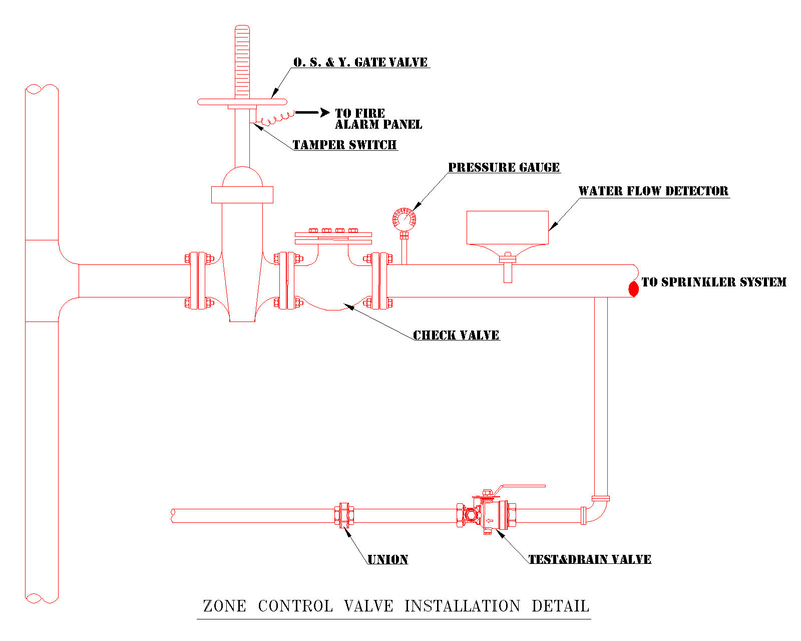
Zone Control Valve Installation Detail — Sprinkler Floor Control Assembly
Elevation of a sprinkler zone control valve assembly taken off the riser, showing an OS&Y gate valve with supervisory tamper switch, check valve, pressure gauge, water flow detector and the test and drain line with union.
About
What this drawing shows
A zone control valve assembly, also called a floor control valve assembly, drawn in elevation as it branches off the sprinkler riser. In order of flow, the branch passes through an OS&Y gate valve fitted with a supervisory tamper switch wired to the fire alarm panel, a check valve, a pressure gauge and a water flow detector before continuing to the sprinkler system. A test and drain line leaves the assembly downstream of the flow detector and drops to a test and drain valve, with a union for removal.
This is the arrangement repeated on each floor or zone of a multistorey sprinkler system, so that one zone can be isolated, drained and tested without shutting down the rest of the building, and so that the fire alarm panel can report which zone is flowing.
Installation notes
The position of the test and drain connection matters more than anything else on this detail, and the drawing has it right: it leaves the pipe downstream of the flow detector. Testing has to push water past the flow switch, otherwise the weekly or quarterly test proves the valve opens and nothing else. On site this gets reversed surprisingly often, usually because the drain branch was fabricated before anyone decided where the flow switch would sit. The test valve should be a combined test and drain valve with a sight glass and a test orifice matching the smallest sprinkler on that zone, so that opening it simulates one sprinkler operating. Its discharge has to go to a drain riser sized to take the full drain flow, not the nearest floor gully — a drain that backs up floods the riser cupboard every time the system is tested, and after the second time nobody tests it.
The tamper switch is a supervisory device, and it must report to the fire alarm panel as a supervisory signal, not as a fire alarm and not as a trouble signal. NFPA 72 treats these differently and so should the panel programming. The commonest commissioning finding is a valve switch wired into an alarm zone, so partly closing the valve during maintenance evacuates the building; the second commonest is a switch that only operates when the valve is fully shut, when it should signal as soon as the valve starts to close. Check the switch actuates within the travel required by the standard for your edition, and test it from open, not from closed. The flow detector needs its retard adjusted so that a pressure surge in the supply does not trigger an alarm, but not so long that a real single-head flow is delayed beyond what the code allows.
Two coordination points are routinely missed at design stage. An OS&Y valve has a rising stem, so it needs vertical clearance above the handwheel for the stem to travel fully open, and in a shallow riser cupboard or under a beam the valve is installed and then cannot be fully opened. The whole assembly also has to be reachable: the handwheel, the test valve and the flow switch cover all need access without a ladder over other services, and the valve must be visible so an inspector can confirm its position at a glance. NFPA 13 requires floor control valve assemblies in multistorey buildings above a stated number of storeys; check the edition enforced on your project, and note that Saudi Civil Defence requirements may be stricter than the referenced standard, including on valve room access and labelling.
Whether the check valve is needed depends on the system. Where a zone can be fed from more than one direction, such as a looped or gridded arrangement or a building with two risers interconnected, the check valve stops a closed zone being back-fed. On a simple single-riser tree system it is sometimes omitted. Keep it on the detail if you are unsure — but make sure the pressure gauge sits where it reads the zone side, so that when the zone is isolated and drained the gauge confirms it.
Drawing use
- Typical details for sprinkler riser and floor control valve arrangements
- Civil Defence submittals and fire alarm interface coordination
- Method statements for zone isolation, testing and draining
Confirm the test orifice size, drain riser capacity and the supervisory signal programming against the standards governing your project before issuing.