 DWG
DWG
Wet Fire Hydrant Installation Details — PIV, Hose House and Guard Posts
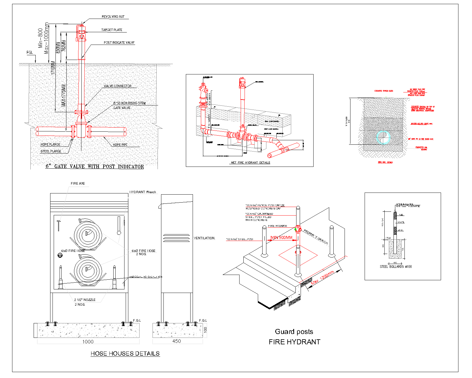
Fire hydrant installation sheet covering a wet barrel hydrant on an HDPE lateral in isometric, a gate valve with post indicator, an HDPE pipe trench section, a hose house in front and side elevation, and guard post and steel bollard…
Screenshots

About
What this drawing shows
A sheet of external fire hydrant details. The wet fire hydrant detail is an isometric of a wet barrel hydrant connected by an HDPE lateral to the fire main, with the branch taken from the main, a gate valve with post indicator on the lateral, thrust blocks at the valve and at the hydrant base, and first and final backfill layers shown against finished ground level. Outlet height above ground and burial depth are dimensioned as minimum and maximum ranges.
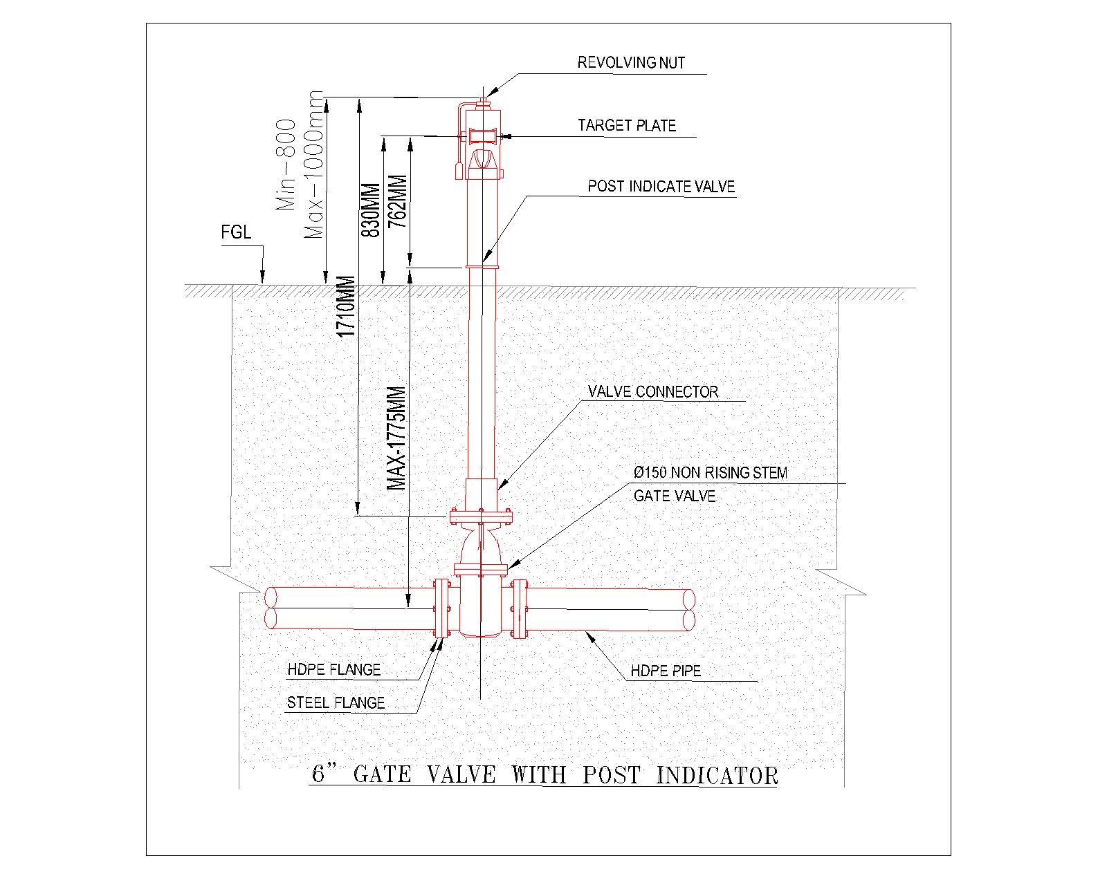
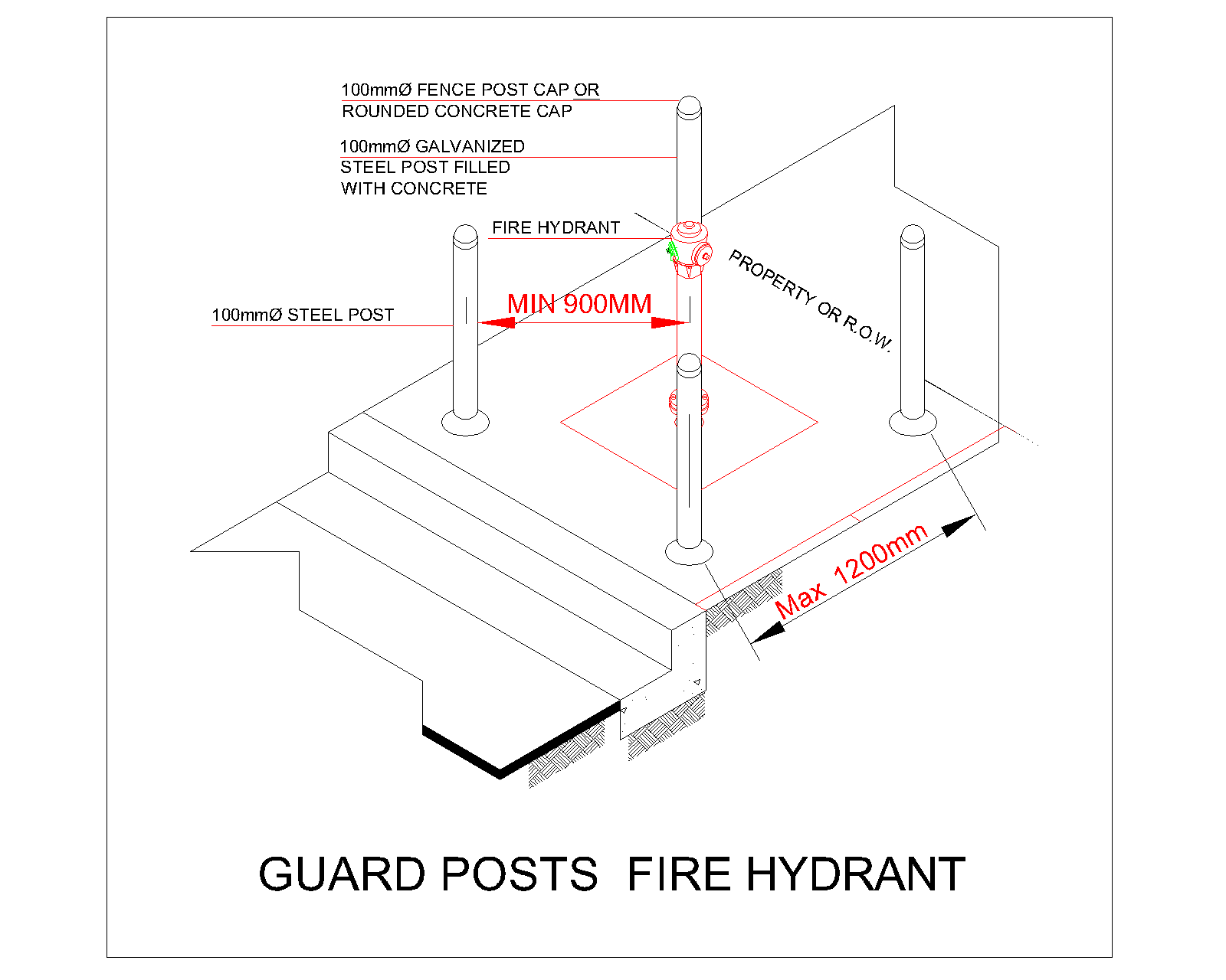
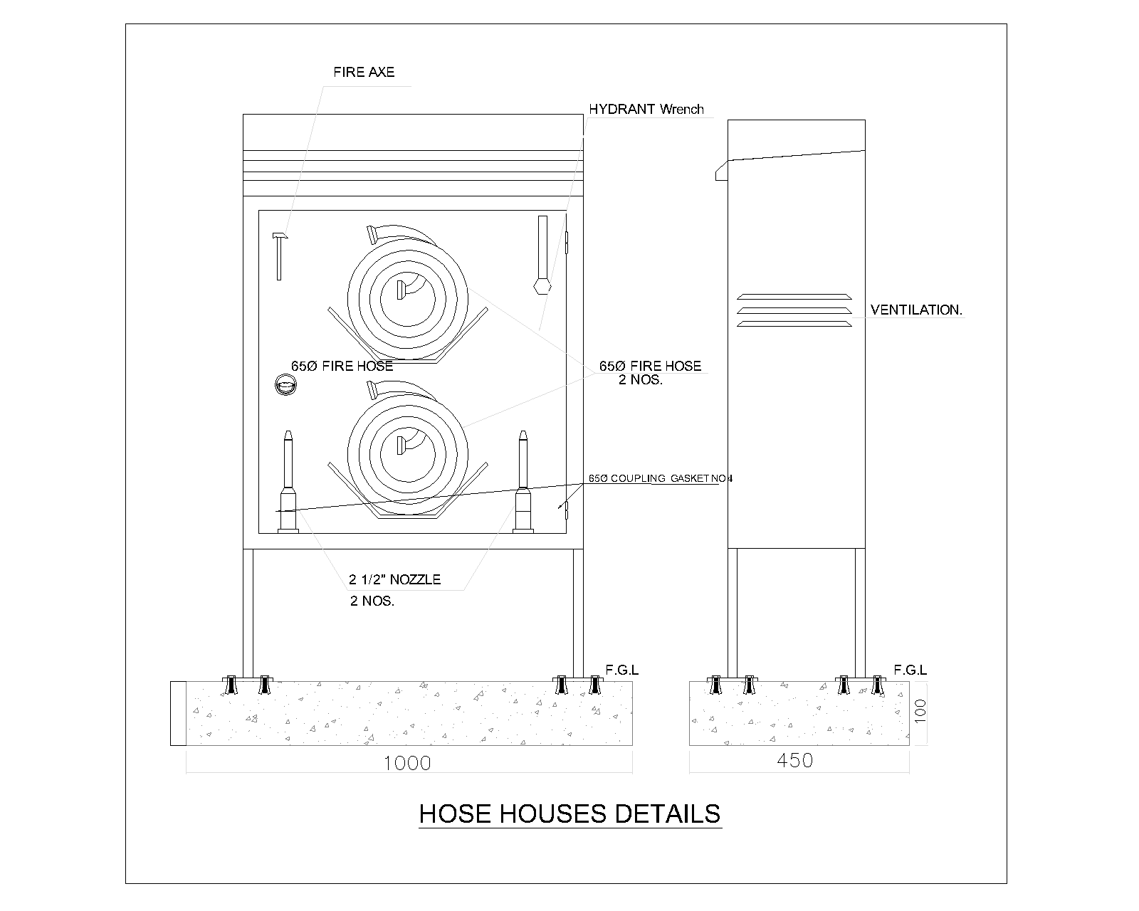
The post indicator detail is a section through a non-rising stem gate valve on an HDPE main, with the valve connector, extension and indicator post rising to a target plate and operating nut above ground, and the transition from HDPE to steel flange at the valve. A trench section shows the HDPE fire main with bedding, selected backfill and compaction layers. The hose house is drawn in front and side elevation on a concrete base, fitted with two 65 mm fire hoses, two nozzles, a hydrant wrench, a fire axe, spare coupling gaskets and ventilation louvres. The protection details show concrete-filled galvanised steel guard posts around a hydrant set back from the kerb, and a steel bollard section with its foundation.
Installation notes
The transition between HDPE and the ductile or steel valve body is the weak point of this arrangement, and it is where the underground main usually leaks. HDPE connects to a flanged valve through a stub end and a loose steel backing ring, and HDPE creeps under bolt load, so the flange bolts lose tension after installation. They need tightening to the pipe manufacturer’s procedure and checking again before backfill, not torqued once and buried. A fully fused HDPE run is self-restrained, which is why people assume it needs no thrust blocks, but the moment the line changes to flanged or mechanical joints at a valve, a tee or the hydrant shoe, that restraint stops. Thrust blocks are needed at those points, poured against undisturbed soil rather than against backfill. A block cast against loose fill moves on the first pressure test and pulls the joint apart.
HDPE is also invisible to a cable locator. Lay a tracer wire along the main, brought up at valve boxes and hydrants, and a warning tape above it in the backfill. Without them the fire main is found by the next excavator on site, and on a campus or compound in the Kingdom where services are routinely added years after handover, that happens more often than it should. The trench section on this sheet shows the bedding and backfill layers; the material, layer thickness and compaction come from the pipe manufacturer and the project specification, and the first layer around the pipe must be free of stones that will point-load the wall.
Wet barrel hydrants suit the climate here. There is no frost risk, so the barrel stays full to the outlet valves and each outlet can be opened independently, which a dry barrel hydrant does not allow. Outlet height above finished ground matters in use: too low and the hydrant wrench cannot turn a full circle and the hose kinks at the coupling; too high and the pumper connection strains the barrel. The drawing gives a range, and NFPA 24 and the local Civil Defence authority set the requirement — confirm it for your project. Face the pumper outlet towards the fire lane, and check that the hose thread matches what the local fire service carries. For the post indicator, the target plate must be readable from the approach, the operating nut reachable without stepping into a planted bed or over a kerb, and the valve supervised or locked in the open position as the standard requires.
Guard posts protect the hydrant from vehicles, but they are only correct if they do not obstruct it. The posts must leave room for the hydrant wrench to swing through a full turn on every outlet, and for a hose to be connected and led away from the pumper outlet without a kink. A post placed directly in front of the pumper outlet is a common site mistake — it protects the hydrant so well that the fire service cannot use it. Keep the posts clear of the outlets and set them where vehicle approach is actually likely. The hose house needs the same thinking: doors that open fully against any adjacent wall, a base above flood level, and equipment checked against the inventory on the door during routine inspection, because hose houses are where hoses and nozzles go missing first. Hydrant spacing, set-back from the building and kerb, and hose house provision are all set by NFPA 24 and by Saudi Civil Defence, and local Civil Defence requirements may be stricter than the referenced standard.
Drawing use
- External fire main and hydrant details for site and infrastructure drawings
- Civil Defence submittals for private fire service mains
- Method statements for HDPE fire main installation, testing and backfilling
Confirm hydrant outlet height, burial depth, spacing and set-back against NFPA 24 and the local Civil Defence requirement before issuing.