 DWG
DWG
Deluge Valve Assembly Detail — Trim, Release and Drain Arrangement
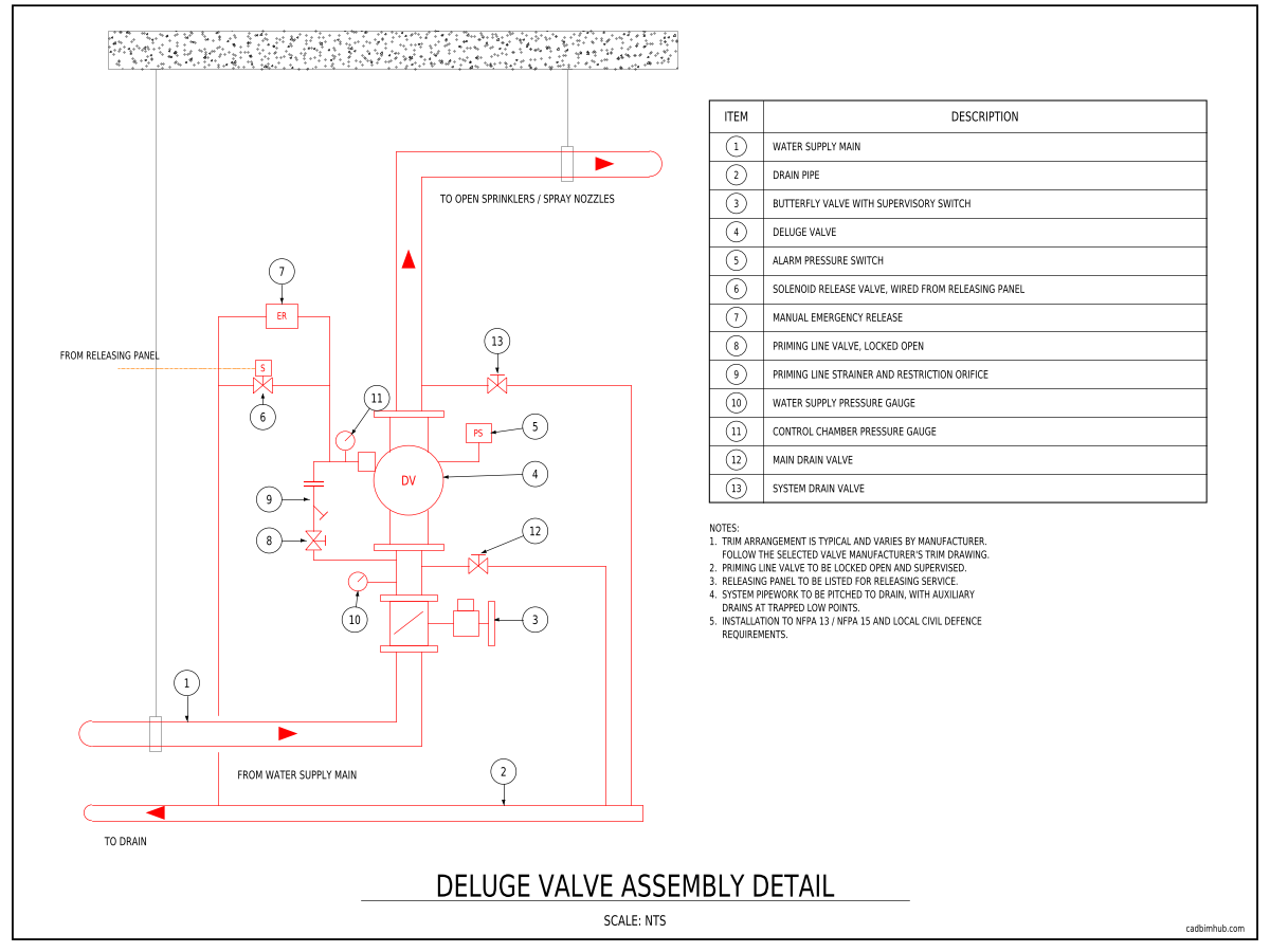
Schematic elevation of a deluge valve assembly with thirteen numbered items, covering the butterfly control valve with supervisory switch, the priming line with locked-open valve, strainer and restriction orifice, solenoid and manual emergency release, alarm pressure switch, supply and control…
About
What this drawing shows
A schematic elevation of a deluge valve assembly rising from the water supply main, with pipe supports hung from the slab above and a numbered item table beside it. The supply passes through a butterfly control valve fitted with a supervisory switch and into the deluge valve, then continues to the open sprinklers or spray nozzles of the system.
The trim is drawn in full. A priming line is taken from the supply side below the valve, through a priming valve locked in the open position, a strainer and a restriction orifice, into the control chamber. Two release paths leave the control chamber in parallel — a solenoid release valve wired from the releasing panel and a manual emergency release — and both discharge to drain. The assembly also carries an alarm pressure switch, a water supply pressure gauge, a control chamber pressure gauge, a main drain valve on the supply side and a system drain valve on the outlet side, all connected to a common drain pipe. Notes on the sheet cover priming line supervision, the releasing panel listing, system drainage and the governing standards.
The detail is deliberately schematic and not tied to any one manufacturer. The valve body and trim components are drawn as simple shapes so the arrangement reads clearly on a submittal; replace them with the selected manufacturer’s trim drawing where a project calls for it.
How a deluge valve works
Unlike an alarm check or dry pipe valve, a deluge valve feeds a system of open sprinklers or spray nozzles, so when the valve opens, water discharges from every head on the system at once. The valve is held shut by water pressure in its control chamber, supplied through the priming line. Releasing that pressure — through the solenoid when the detection system operates, or through the manual emergency release — lets the supply pressure open the valve.
Installation notes
A deluge valve does nothing on its own; something has to release it. That is usually the solenoid shown here, energised by a releasing panel responding to heat, flame or smoke detection, or a pilot line of closed sprinklers that loses pressure when one operates. The releasing panel must be listed for releasing service, not just an ordinary fire alarm panel with a spare output, and because an unwanted operation floods the whole area, detection is often cross-zoned so that two detectors must operate before release. The manual emergency release needs to be where someone can reach it safely during a fire — outside the hazard, at the exit or at a protected position away from a transformer, not bolted to the valve inside the room it protects. A deluge trim detail without its release arrangement will be returned at review, which is why both release paths are drawn here.
The control chamber is where these valves are lost. If the priming valve is left closed after maintenance, chamber pressure decays and the valve can trip on its own; if the strainer or restriction orifice blocks, the valve cannot be reset. That is why the priming valve is shown locked open and should be supervised, and why the detail carries two gauges — compare the supply and control chamber readings at every inspection against the relationship the manufacturer specifies. After a trip, most deluge valves latch open and must be reset by hand following the manufacturer’s procedure, so the reset steps belong on a sign at the valve, not in a manual in the site office.
Everything downstream of the valve is dry, open to atmosphere and full of air, and it has to drain completely after every operation or trip test. Slope the system pipework back towards drains, fit auxiliary drains at every trapped low point, and route the main drain, system drain and release discharges to a point able to take the full flow. Water left sitting in dry pipework corrodes it from the inside and blocks nozzles with scale, which on a water spray system is the failure that matters most. NFPA 25 requires periodic full-flow trip tests, which means flooding the protected area — plan for that at design stage with drainage, bunding or containment, particularly around transformers where the run-off may carry oil.
The butterfly control valve’s supervisory switch must report to the fire alarm panel as a supervisory signal, not as an alarm, and the alarm pressure switch reports water flow when the valve opens. Hydraulically, a deluge system is sized for every head flowing together, so its demand is often the largest on site and governs the fire pump and water supply. System design and installation fall under NFPA 13 or NFPA 15 depending on the application, and local Civil Defence requirements in the Kingdom may be stricter than the referenced standard.
Drawing use
- Deluge and water spray system details for transformer, conveyor, loading bay and hangar protection
- Valve room layouts and Civil Defence submittals
- Coordination with releasing panels, detection and drainage
Confirm the release arrangement, trim components and drain routing against the selected valve manufacturer’s data and the standards governing your project before issuing.