 DWG
DWG
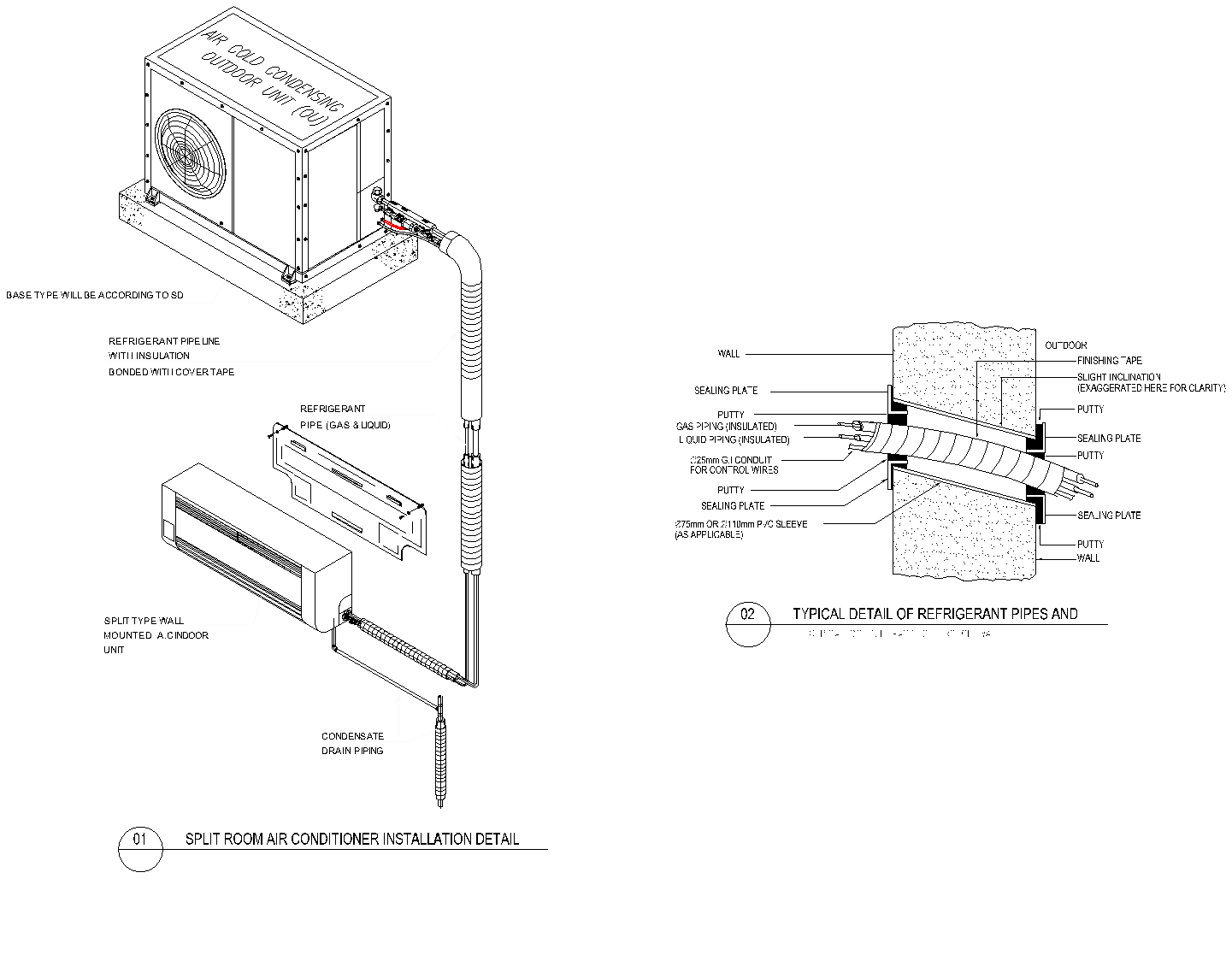
Split Room Air Conditioner Installation Detail with Wall Penetration Section
Two-part detail showing a complete split room air conditioner installation — outdoor condensing unit on a plinth, wall mounted indoor unit, interconnecting refrigerant lines and condensate drain — together with a section through the wall penetration showing sleeve, sealing plates…
About
What this drawing shows
Detail 01 is an isometric of a complete split room air conditioner installation. The air-cooled condensing unit sits on a plinth with the base type left to the structural drawings, the refrigerant gas and liquid lines run insulated and bonded with cover tape from the service valves down to the wall mounted indoor unit, and a separate condensate drain line leaves the indoor unit. The indoor unit is shown with its mounting plate, and the pipe entry point behind the casing is drawn so the wall opening can be set out before the plate is fixed.
Detail 02 is a section through the wall penetration. It shows the insulated gas and liquid lines and the control wiring conduit passing through a PVC sleeve, with a sealing plate and putty on both faces and finishing tape on the outdoor side. The sleeve is drawn with a slight fall towards the outside, exaggerated on the drawing for clarity. Sleeve and conduit sizes are annotated on the drawing itself — check them against your own project specification before issuing.
Installation notes
The fall on the wall sleeve is the single most ignored item on this detail. The sleeve must slope down towards the outdoor face so that any water entering the penetration, whether driven rain or condensate running along the insulation, drains outwards. Drilled level it holds water; drilled with fall towards the room it delivers water straight onto the plaster behind the indoor unit, and the stain appears months later when nobody connects it to the air conditioner. Site teams drill from the inside with a core rig held horizontal because that is easier, then seal both ends with putty and assume the putty is doing the work. The putty is a seal, not a drainage strategy. Set the fall at drilling stage and the detail behaves; correct it afterwards and you are re-coring a finished wall.
Where this penetration passes through a fire rated wall, the arrangement drawn here is not sufficient on its own. A PVC sleeve, a sealing plate and putty are a weatherproofing and neatness detail. A fire rated penetration needs a listed firestop system tested for that wall construction and for the services passing through it, and that matters especially here because both the PVC sleeve and the closed-cell pipe insulation are combustible and will burn back from the fire side. Intumescent collars or wraps sized for the sleeve diameter are the usual answer, and the sleeve, the pipe, the insulation and the seal must all belong to one tested assembly rather than three products chosen separately. Civil Defence inspectors in the Kingdom look at exactly this junction on MEP walkdowns, and local requirements may be stricter than the referenced standard.
Insulate the gas and liquid lines separately, each with its own continuous sleeve, before bonding them together with cover tape. Taping both bare lines inside a single common insulation sleeve is quick and it is wrong — the liquid line warms the suction line, capacity drops, and the outer surface of the pair sweats because the liquid line is no longer isolated from the warm side. On the outdoor run, the cover tape alone will not survive Riyadh sun. Standard PVC tape and unprotected elastomeric insulation chalk, split and fall away within a season or two of direct exposure, after which the bare line sweats and drips down the façade. Specify a UV resistant finish, painted UV coating or metal cladding on every exposed section, and keep the run out of standing sun where the layout allows it.
On the condensate side, the drain needs continuous fall from the indoor unit spigot to its termination, and it needs terminating somewhere deliberate. Dropping the line onto the façade or over a parapet is normal on site and causes staining, nuisance and, on a residential block, complaints from the floor below. Take it to a floor drain, gully or dedicated condensate riser. Trap the drain where the indoor unit sits under negative pressure, otherwise air is drawn back up the line and water sits in the pan instead of leaving it. For the refrigerant pipework, the vertical lift between indoor and outdoor units and the total equivalent pipe length are both limited by the manufacturer, and exceeding them costs capacity and oil return — take the figures from the selected model’s data, not from a standard detail, and where the outdoor unit sits above the indoor unit check whether the manufacturer requires oil traps on the riser. Run the control wiring in its own conduit as drawn, and fit a lockable isolator within sight of the outdoor unit so the service engineer is not relying on a distribution board three floors away.
Drawing use
- Typical detail sheets for split and multi-split air conditioning installations
- Method statements and material submittals requiring a wall penetration section
- Coordination drawings where pipe entry points and outdoor unit plinths need setting out
Sleeve, conduit and insulation sizes on this detail should be confirmed against the project specification and the selected equipment before the drawing is issued for construction.