 DWG
DWG
Fire Hydrant CAD Block — Front, Side and Top View
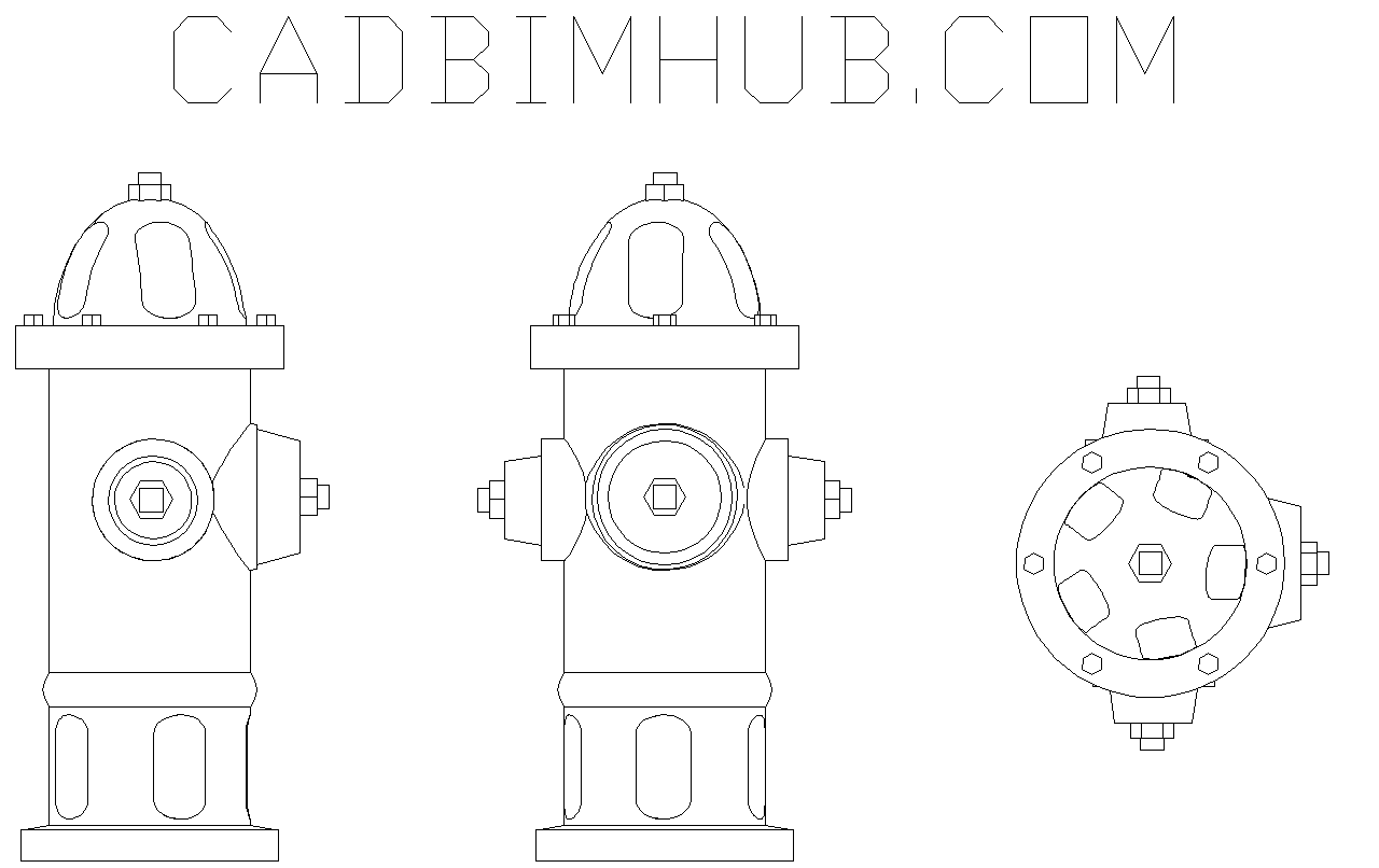
Pillar-type fire hydrant block in front, side and top view, showing outlet arrangement, operating nut and flange base.
About
A pillar-type fire hydrant drawn as a component block in three views: front, side and top. The views show the outlet arrangement, the operating nut on the bonnet and the flanged base where the hydrant meets its riser.
Views included
- Front view — bonnet, operating nut, pumper outlet and flange base
- Side view — both hose outlets and the outlet caps
- Top view — bonnet plan with outlet positions
How to use it
Use the top view on a site plan to set the hydrant position and check clearances, and the front or side view on an elevation or section.
The block is drawn in metres. Most MEP drawings are set up in millimetres, so inserting it directly into one will place it at a thousandth of its real size. Either set the insertion scale to 1000, or use INSERT with the block units left to scale automatically — AutoCAD will convert it if the drawing’s INSUNITS is set correctly.
Check the block against the hydrant actually specified for your project before issuing. Outlet count, outlet size, thread type and overall height vary between manufacturers and between jurisdictions, and the attending fire department’s coupling is the thing that has to match.
Applicable standards
- NFPA 24 — Private Fire Service Mains and Their Appurtenances
- Check local Civil Defence requirements for hydrant type, spacing and outlet threads